DFM or Design for Manufacturing is just a fancy word for what design is easier for manufacturing. This depends not only on the design but also on the manufacturing capability. Manufacturing capability varies from company to company, quantity to quantity, and from price to price.
In the early generations of the iPhone, to hold the camera firm enough and also provide enough flexibility for the anti-vibration function, the camera mount design requires 4 thin steel wires with a diameter of about 0.1 mm. This is normally considered to be not manufacturable, but Foxcom – the OEM for iPhone spent 3 months on research and finally made them, and made them in large quantities.
If the production quantity were not in millions, almost all manufacturers will turn this order down as it would not be worth the effort of a 3 months research (and when they do the research they did not know how long it would take. ). The point here is that the manufacturing capacity is not a fixed point, something not very ‘DFM’ can be manufactured when enough incentives are given.
That has been said. In the following sections, we will talk about the common DFM features for CNC production under the general level of manufacturing capability. And why they are hard to manufacture.
Undercut
It literally means we have to cut some material under something. The blue area of the picture below is what is called an undercut. It is hard for CNC to make simply because tools are straight and can not reach the area without interference with the top area. However, not all undercuts are not madible. If there is enough room for a T-bar tool to work, the undercut can be manufactured. For CNC lathing, if there is enough room for a hook-like tool to work, the undercut also can be made. Of course, that also means you have to be familiar with the size and specs of those tools to decide if the undercut is good for manufacturing. Nonetheless, undercut is considered not a good DFM feature.
Sharp corners:
CNC tools are round. They could only cut a round corner. So a sharp corner is considered not a good DFM for CNC. But it does not mean the sharp corner is totally not manufacturable, EDM and EDM wire cutting are often applied to make sharp corners, but of course, they cost much more than CNC. Therefore, design round corners as long as it is possible.
Thin Wall thickness
When CNC tools remove material from metal stock, it pushes metal away. The force it creates can deform the wall left if the wall’s thinness is not enough. How thin is ‘thin’? It depends on the height of the wall and also the material, for the CNC lathing part, we also have to think about the clipping diameter. Thinner wall thickness can be obtained for stainless and carbon steel parts, on the other hand, copper, brass, and aluminum are much easier to deform. In general, we think any wall thickness below 1mm is not a good DFM. But again, it does not mean it is absolutely not possible to make a 0.5 mm wall thickness in an aluminum part. Just in general, try to avoid very thin walls when designing metal parts.
Small diameter holes
With some special gears or technic, we can drill a hole with 0.5mm diameter, but it is very difficult, the chance is the tool is going to break. Any hole with a diameter less than 1 mm is considered not a good DFM for CNC. We can still try EDM wire cut or EDM, or even just hand drill the hole but in general, trying to avoid designing such small holes is a good practice.
Deep holes
When the diameter/depth ratio of a hole is small enough, we have to consider the rigidity of the drilling tool (or lathing tool in case of lathing parts), the chip management (especially for blind holes), heat dissipation, the stock material, and the tolerance of the hole. In plain English, if the hole is too deep relative to its diameter, the drilling tool is going to bent so is the path, chips are hard to be removed and cause problems, and heat dissipation is hard too, which could cause the tool to be annealed or over quenched. All these could affect the tolerances. And harder materials such as stainless steel, carbon steel, and titanium suffer more sever from deep holes than softer materials like copper, brass, and aluminum. And also there are problems with tool availability and cost, as deeper holes require harder tool material and hence cost more.
Generally speaking, when the diameter/depth ratio of a hole is bigger than ⅕, there is no problem for almost any material. ⅕~⅛, we start to see some tolerance issues for some hard material, but still manageable. ⅛ ~ 1/12, high tolerance is very hard to get, and we start to see a serious problems like tool broken, bent holes, cone-shaped holes, etc. Below 1/12, special tools and machines are suggested.
Again, deep holes are considered to be bad DFM, but not totally impossible to make, it depends on the cost, equipment, and time one like to invest in.
Narrow Slit
Same as small diameter holes, too narrow slit requires too small diameter milling tools and is easy to break. Same as deep holes, tall, narrow slits require long milling tools and suffer the same problem as deep holes. When designing parts, try to avoid any slit less than 0.8mm or width/depth ratio less than ⅛.
Tolerance:
Tolerance at +/-0.05 mm for a 50 mm diameter is much easier to achieve than for a 500 mm diameter. Any tolerance should be discussed relative to its base size. Obviously, for the same tolerance requirement, the larger the base size, the harder to achieve. For CNC machining service, for metal parts, we apply ISO2768 medium as a standard for any size without specific tolerance requirement, and ISO2768 coarse for plastic parts.
For tighter tolerances, both quantity and quality matter, the quality here means how small the tolerance range is, and quantity is how many places tighter tolerances are applied. Two tolerances requirement at +/- 0.02 mm in one part is much harder than one. A 0.01 mm tolerance is obviously harder to get than 0.02 mm.
Generally speaking, +/-0.01 mm tolerance or equivalent for a medium size part (let us say about 100 mm or less) is about the limit of a reasonably good CNC manufacturer.
For a good DFM design, try to apply tolerance tighter than ISO 2768 as less as possible. And if possible try not to use any tolerance tighter than +/-0.01 mm.
Again, a tolerance tiger than +/-0.01 is not absolutely not achievable. We have manufactured aluminum parts with a tolerance range of 0~0.015 mm for high-speed bearing blocks in a small volume. And 0.006mm tolerance for the precise shaft in a massive volume. But it will need extra care, technic, complicated processes, and sometimes good working environment control.
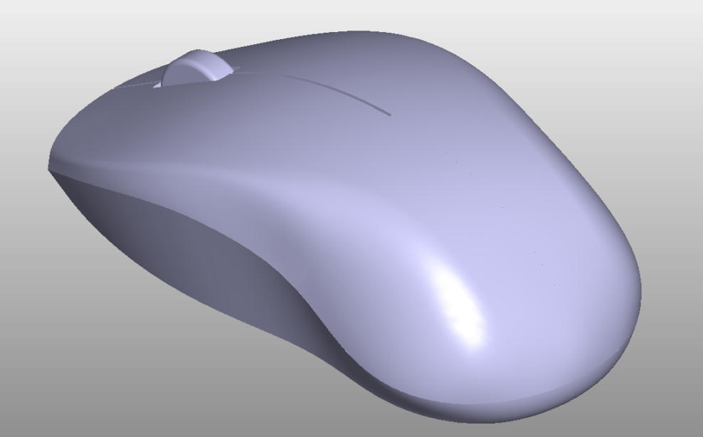
Complex Curved Surfaces
A surface is cut into 2 curves by 2 normal sections. If none of these 2 curves is either a straight line or an arc then the surface is a complex curved surface. No straight line means the CNC machine can not apply a normal flat-end milling tool, no arc means a CNC lathing process is out of the question. That means we have to use a ball cutter to form the surface micron by micron. It takes a lot of time and hence it is much more expensive. Therefore, for a good DFM, only use complex curved surfaces when it is absolutely necessary.
Internal Stress Deformation
“Stress” is a kind of force, imagine a piece of metal or plastic formed by small sections, internal stress literarily means the forces among those sections. When we remove some sections to make a part, some of this internal stress disappears, and the material deforms. It would not be a noticeable problem if the stress was not strong or not too much material is removed. But for rather large stock material and a relatively big proportion of the material removed, there will be noticeable deformation in the final parts. There are methods to deal with such problems when manufacturing. We could anneal the material to release some stress before machining, or we could do an aging process between processes, or we could cut less material then do aging, and then cut the remaining materials. All these methods take time and cost.
A design tip to reduce the effect of internal stress deformation is ‘spins’, instead of removing all the materials in a certain area, leave some ‘spins’ left, this could reduce the chance of deformation. The design on the left is a better DFM design than the one on the right.