Basic Guide to Injection Molding Processing
Basic Guide to Injection Molding Processing
By: CapableMaching
Preface:
This concise guide is designed to provide a simple introduction to the basic aspects of injection molding. Whether you are new to the field or looking for a quick reference, this page covers the basics, machine operation and optimization. Injection molding is a key player in the manufacturing industry, shaping products ranging from everyday items to industrial parts. This guide strives to simplify the complexity and provide practical insights into effective and efficient molding processes. Whether you’re a student, engineer, or industry professional, we hope this guide will be a handy resource to help you navigate the world of injection molding.
An “injection cycle” can refer to different processes depending on the context, but one common meaning of injection cycle is in the context of injection molding, a manufacturing process used to produce plastic parts. In injection molding, an injection cycle refers to the sequence of steps that occur to produce a single part or product.
To understand the detailed process of injection molding and how to adjust the corresponding parameters of the injection molding machine, we must theoretically understand how the plastic flows.
In order to produce high-quality products, it is necessary to understand the details of the injection molding process and how to adjust the corresponding parameters of the injection molding machine, which requires that we must understand how the plastic flows in the machine, which in turn, we have to know the theories and terminology in this area.
Fountain Flow Theory
The Fountain Flow Theory is named after the way the molten plastic material behaves as it enters and fills the mold cavity. In this theory, it is assumed that the plastic material flows into the mold in a manner similar to the flow of a liquid in a fountain. [1] Here’s a simplified explanation of the concept:
A). Entry Point: The plastic material enters the mold cavity at a single entry point or a few entry points. This entry point is typically called the gate.
B). Flow Pattern: As the material is injected through the gate, it moves outward and upward within the mold cavity, similar to the way water rises and spreads when a liquid is pumped into a central point, creating a fountain-like flow pattern.
C). Filling Behavior: The molten plastic flows through the mold cavity, following this fountain-like pattern, and fills the intricate details of the part as it progresses. This flow behavior is critical in ensuring that even complex and thin-walled sections of the part are adequately filled.
The Fountain Flow Theory is an important concept for mold designers and process engineers in injection molding. Understanding how the material flows within the mold cavity is crucial for achieving uniform part quality, minimizing defects like air pockets or short shots, and optimizing cycle times.
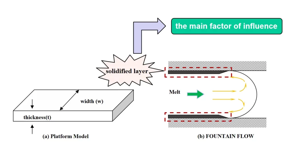
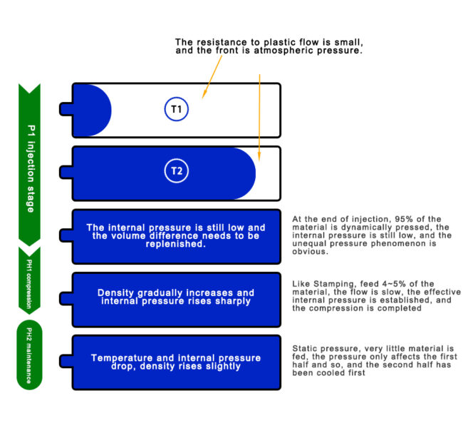
Generally, injection molded products are flat products with thin wall thickness. A flat product is defined as a product with a thickness of 3 to 4 mm or less and a width of 5 times the thickness.[2]
In this kind of CAVITY, the resin flows and produces a solidified layer on the mold to form a water-splitting mold in advance.
According to this principle, the metered resin at the front end forms the surface part of the product and the metered resin at the back end fills the center part of the product.
Shear deformation rate and friction heat
The shear deformation rate, often denoted as γ (gamma), is a fundamental concept in fluid mechanics and rheology that describes how different layers or elements of a fluid move relative to one another, creating shear or deformation within the fluid. In the context of fountain flow theory in injection molding, shear deformation rate is relevant because it helps describe how the molten plastic material deforms as it flows within the mold cavity.
In fountain flow theory, shear deformation rate refers to the rate at which adjacent layers or particles of the molten plastic experience relative motion or deformation as the material flows through the mold cavity. This deformation rate is influenced by factors such as the injection speed, the viscosity of the plastic material, and the geometry of the mold.[3]
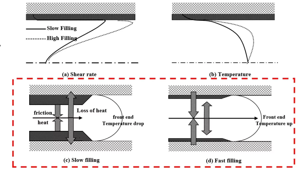
When the injection speed is slow, as the material enters the interior of the mold farther and farther, the loss of heat is greater, at this time, the shear deformation rate is reduced, and the friction heat generated is smaller, the result is that the product surface curing layer becomes thicker, which will ultimately affect the growth of the product.
Injection speed is fast, the material into the interior of the mold, the loss of heat is small, at this time the shear deformation rate is increased, and the friction heat generated will increase, the result is that the product surface of the curing layer becomes thinner, but will increase the cooling time of the product is less efficient, and at the same time, will produce a variety of defects (such as batch fronts) and so on.[4]
Injection pressure
Injection pressure, in the context of injection molding, refers to the force or pressure applied to push the molten plastic material into the mold cavity during the injection phase of the molding process. It is one of the key parameters controlled by the injection molding machine and is a critical factor in determining the quality and consistency of the molded parts.
Injection pressure is typically measured in pounds per square inch (psi) or megapascals (MPa) and can vary based on factors such as the material being used, the geometry of the part, and the design of the mold.
The magnitude of the injection pressure required depends on several factors, including:
a) Material Viscosity: More viscous (thicker) materials require higher injection pressures to flow properly.
b) Mold Design: The complexity and size of the mold, as well as the number and design of the cavities, can influence the required pressure.
c) Part Geometry: Thin-walled or intricate parts may require higher pressure to fill properly.
d) Injection Speed: Faster injection speeds often require higher pressure to maintain flow.
e) From a safety perspective, during production, a pressure smaller than the maximum injection pressure of the injection molding machine should be used until the end point of the cavity is filled. Generally, the injection pressure is less than 80% of the maximum injection pressure of the injection molding machine.[5]
Fill time
In injection molding, “fill time” refers to the duration it takes for the molten plastic material to completely fill the mold cavity during the injection phase of the molding process. This parameter is a crucial aspect of the molding process and is typically measured in seconds or milliseconds. Fill time is one of the key factors that influence the quality and consistency of the molded parts.
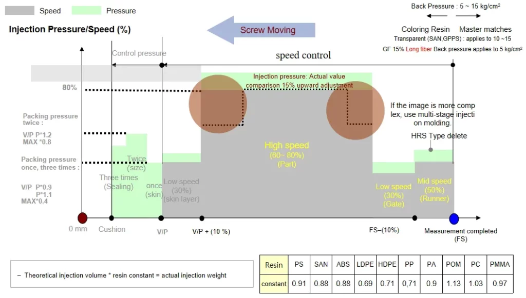
The relationship between injection speed and injection pressure is shown in the graphic as a U-shaped curve. If the injection speed is slow, the heat loss is high, the flow temperature decreases, the viscosity increases, the thickness of the curing layer increases, so the flow resistance is high and the injection pressure increases.
On the contrary, if the injection speed is fast, the flow temperature rises, the viscosity decreases and the thickness of the curing layer becomes smaller. However, the frictional resistance between the curing layer and the flow layer increases considerably, which in turn increases the injection pressure. The injection pressure is minimized when the flow rate in Caviti is constant.[6]
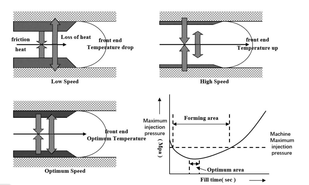
The optimum injection speed is the one that minimizes the injection pressure under the given conditions. Depending on the thickness of the cavity, the injection speed should be different. Thin ones have a smaller effective flow section than thick ones. Therefore, it is necessary to increase the injection speed, increase the deformation rate of the whole section, and increase the friction deformation force in order to stabilize the flow temperature and reduce the injection pressure. [7]
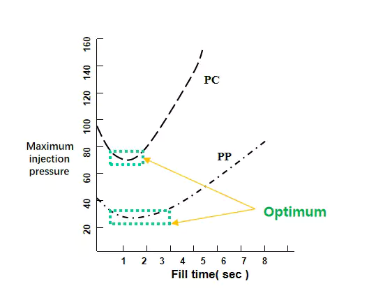
Depending on the material of the resin, the specific heat, thermal conductivity, viscosity, etc. can vary greatly. Depending on the temperature, materials with high viscosity changes (PC, PMMA) have a smaller U-arc, but materials without that property (PP, ABS) have a larger U-arc. So some materials are sensitive to injection speed and some are not.
Holding Pressure Setting
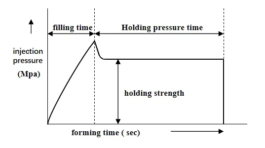
Holding pressure refers to the injection into the material after the cavity in order to ensure that the resin cooling shrinkage is not too large, in the appropriate time to advance the screw in order to maintain the appropriate pressure in the cavity, continue to provide the resin to the process of the cavity, and to compensate for the cooling of the molten plastic material curing contraction, this process has a great impact on the quality of the product.
Determination of holding pressure strength and time
Holding Strength: The amount of holding pressure determines the amount of shrinkage. Generally, if the holding pressure is increased, the product will become fuller and prevent shrinkage from occurring. If the holding pressure is too low, the product will become smaller in size and shrinkage will occur. However, too high a holding pressure will increase the shape force and residual hardness, which will deform the product. Generally, the appropriate holding pressure is 70~80% of the maximum injection pressure.
Holding pressure time : Holding pressure time has a lot to do with the thickness of the cavity. Because the thicker the product is, the longer the cooling time is, and in order to prevent shrinkage, the resin needs to be supplied all the time during that time, so it is necessary to hold the pressure for a certain period of time. However, since the resin cannot enter the cavity after the GATE has cured, the holding pressure will lose its optimal effect, since the resin cannot transmit pressure after the GATE has cured. Here, it is necessary to design the GATE according to the thickness of the product in order to match the holding time, of course, the curing time of the GATE depends on the thickness and length of the GATE. [8]
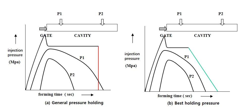
Generally, if the holding pressure is applied evenly according to a certain pressure, the holding pressure near the GATE is large and the shrinkage rate of the product will be small, but when the filling reaches the final part, it is relatively insufficiently subjected to the pressure, and the probability of shrinkage increases greatly, and uneven shrinkage will occur. This unevenness increases the residual stress in the product, which is an important cause of deformation. Therefore, instead of setting the holding pressure at an average pressure, the size of the holding pressure is gradually reduced, and by setting the holding pressure several times, the deviation of the position of the pressure inside the CAVITY can be reduced[9].
In addition, it is also possible to reduce the defects by setting the GATE at the thick part of the product. Generally speaking, the shrinkage rate depends on the pressure and the curing speed. Setting GATE at the place where the curing speed is slow and the shrinkage rate is big, and providing sufficient pressure can keep the shrinkage rate within a small range. Generally speaking, the holding pressure time should be set longer than the GATE curing time. If the holding pressure is set shorter than the GATE curing time, it may cause the screw to back up after the loss of pressure because of the unhardened resin (because usually after the holding pressure project is the metering project), and the resin compressed in the front of the GATE will flow backward, and then the shrinkage rate around the GATE will be larger.
Molding conditions
Injection molding conditions refer to the specific parameters and settings used during the injection molding process to produce molded parts. These conditions play a crucial role in determining the quality, consistency, and efficiency of the molding process. Various factors and settings are considered to achieve optimal results.
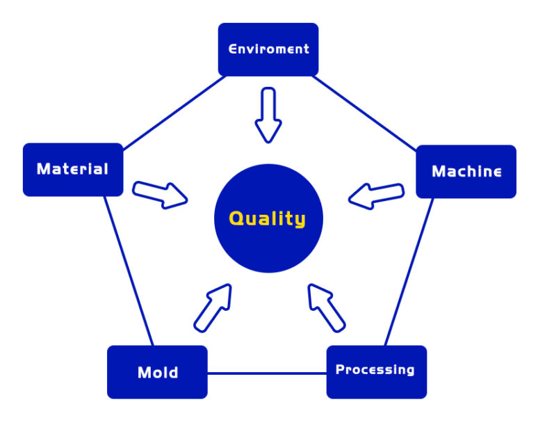
Here are some key injection molding conditions:
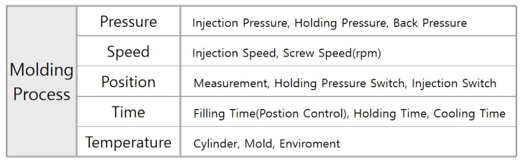
Optimizing these injection molding conditions requires a thorough understanding of the material properties, part design, and mold characteristics. Process engineers and operators carefully adjust these parameters to achieve the desired part quality and to minimize defects during the injection molding process. [10]
Here we must explain some commonly used terms.
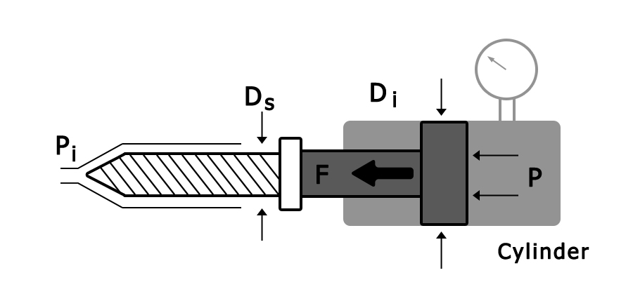
Cylinder
In injection molding, the term “cylinder” typically refers to the barrel of the injection molding machine. The machine’s barrel is a crucial component where the plastic material is melted, mixed, and then injected into the mold cavity to form the desired part. The barrel consists of several zones, each serving a specific function in the plasticizing process.
Mold Temperature
Mold temperature refers to the temperature of the mold in the context of injection molding. It is a critical parameter in the injection molding process and has a significant impact on the quality and properties of the molded parts. The mold temperature is carefully controlled and maintained at specific levels throughout the molding cycle.
Injection speed
Injection speed, in the context of injection molding, refers to the rate at which the molten plastic material is injected into the mold cavity during the injection phase of the molding process. It is a critical parameter that can significantly impact the quality, appearance, and properties of the molded parts. Injection speed is measured in millimeters per second (mm/s) or inches per second (in/s), representing the rate of movement of the injection screw or plunger.
Screw RPM
Screw RPM (Revolutions Per Minute) in the context of injection molding refers to the rotational speed of the screw within the injection molding machine. The screw is a key component in the plasticizing process, responsible for melting, mixing, and injecting the molten plastic material into the mold cavity.
Injection Pressure
It refers to the force or pressure applied to push the molten plastic material into the mold cavity during the injection phase of the molding process.
Packing Pressure
Packing pressure, also known as holding pressure or second-stage pressure, is a phase in the injection molding process where additional pressure is applied to the molten plastic material after the initial injection into the mold cavity. This pressure is maintained for a specific duration during the packing or holding phase of the molding cycle. The primary purpose of packing pressure is to compensate for shrinkage and ensure complete mold filling, contributing to the production of high-quality molded parts.[11]
Back Pressure
In the process of melting and plasticizing plastics, the molten material keeps moving to the front end of the barrel (inside the metering chamber), and more and more, gradually forming a pressure that pushes the screw backward. In order to prevent the screw from moving back too fast and to ensure uniform compaction of the melt, it is necessary to provide a pressure in the opposite direction to the screw, and this pressure in the opposite direction to prevent the screw from moving back is called back pressure.[12]
Screw RPM
The Screw RPM is measured in revolutions per minute, indicating how many times the screw completes a full rotation in one minute.
V/P switchover point
V/P switchover point, also known as Velocity-to-Pressure switchover point, is a parameter in injection molding that refers to the transition point during the injection process when the machine switches from velocity control to pressure control. This transition is important for optimizing the injection molding process and achieving consistent and high-quality molded parts.
During the early stages of the injection process, the machine typically operates in velocity control mode. In this mode, the injection speed is the primary controlled parameter. As the mold fills and the material solidifies, the machine switches to pressure control mode, where the injection pressure becomes the primary controlled parameter.
The V/P switchover point is the point in the injection cycle at which the machine transitions from velocity control to pressure control. This transition is crucial for avoiding issues such as over-packing or under-packing of the mold, which can affect the quality of the molded parts.
Suck back
“Suck back” in the context of injection molding refers to a deliberate retraction or backward movement of the screw during the molding cycle. This is done to reduce or eliminate the presence of molten plastic material at the end of the screw during the cooling and solidification phases of the injection molding process.
The primary purpose of implementing suck back is to prevent drooling or stringing of the molten material after the mold has been filled, and before the mold opens for part ejection. Drooling occurs when excess material remains at the nozzle or in the runner system, leading to the formation of undesired plastic droplets or strings.
Here’s how suck back typically works:
- After the mold is filled, the screw briefly retracts or moves backward.
- This backward movement creates a void or negative pressure at the front of the screw.
- The negative pressure causes any excess molten plastic material at the nozzle or in the runner system to be pulled back into the barrel.
T4. he mold then goes through the cooling and solidification phases without the risk of drooling or stringing.
Suck back is especially useful when working with thermoplastics that have a tendency to string or drool, and it helps in producing cleaner and more precise molded parts. The amount of suck back is typically adjustable, and the optimal setting depends on factors such as the material being used and the specific requirements of the molding application.
Cushion
In injection molding, the term “cushion” refers to the small amount of molten plastic material that is intentionally left in the barrel at the end of the injection stroke. This cushion of material serves several important purposes in the molding process:
- Compensating for Shrinkage: As the plastic material cools and solidifies inside the mold, it undergoes shrinkage. The cushion compensates for this shrinkage by providing additional material that can flow into the mold to fill any voids created by the solidification of the plastic.
- Preventing Short Shots: A short shot occurs when there is insufficient material to completely fill the mold cavity. The cushion helps prevent short shots by ensuring that there is enough material in the barrel to compensate for any variations in the molding process.
3.Avoiding Jetting: Jetting is a defect that can occur when the molten plastic is injected into the mold at a high speed, leading to the material shearing and creating a stream-like flow. The cushion helps to reduce injection speed and pressure, minimizing the risk of jetting.
Hold time
In injection molding, “hold time” refers to the period during which the molten plastic material is kept under pressure in the mold after the injection phase. The primary purpose of the hold time is to ensure that the molded part fully takes the shape of the mold cavity and that any potential issues, such as sink marks or voids, are minimized.
During the hold time, the plastic material in the mold is allowed to cool and solidify under pressure, helping to prevent the material from shrinking or deforming before the part is fully formed. This phase is critical for achieving the desired dimensions, surface finish, and mechanical properties of the molded part.
Key points about hold time in injection molding include:
- Pressure Maintenance: The pressure applied to the molten plastic material is maintained during the hold time to counteract the shrinkage that occurs as the material cools and solidifies. This is particularly important for materials with higher shrinkage rates.
- Gate Freeze: Hold time allows the gate (the point where the molten plastic enters the mold cavity) to freeze or solidify. This helps prevent premature opening of the mold, reducing the risk of flash (excess material) and ensuring that the part is fully formed.
4.Material Cooling: The hold time contributes to the overall cooling of the molded part. The cooling time is a critical factor in achieving consistent and high-quality parts.
Cooling Time
Cooling time in injection molding refers to the duration during which the molded part remains inside the closed mold to allow the molten plastic to cool and solidify. Cooling time is a critical stage in the injection molding cycle and directly influences the quality, dimensions, and properties of the final molded part.
Key points about cooling time in injection molding include:
- Solidification of Plastic: The primary purpose of the cooling time is to ensure that the molten plastic material solidifies completely within the mold cavity. This process is essential for achieving the desired shape and structural integrity of the molded part.
- Minimizing Warpage and Shrinkage: Proper cooling is crucial for minimizing the risk of part warpage and shrinkage. Controlled and uniform cooling helps prevent uneven distribution of stresses within the material.
- Cycle Time Optimization: While longer cooling times may contribute to better part quality, shorter cycle times are generally more desirable for maximizing production efficiency. Balancing cooling time with other factors, such as part design and material properties, is essential.
- Temperature Control: The mold temperature plays a significant role in the cooling process. Many molds have cooling channels through which a temperature-controlled fluid (usually water) is circulated to control the mold temperature and speed up the cooling process.[13]
Clamping Force
Clamping force is a critical parameter in injection molding, referring to the force applied to the mold to keep it closed during the injection and cooling phases of the molding process. The clamping force is essential for maintaining the integrity of the molded part and preventing any plastic from leaking out of the mold.[14]
The clamping force required depends on several factors, including the material being molded, the size and shape of the part, and the injection pressure. There isn’t a universal formula for calculating clamping force because it is influenced by various factors, and different injection molding machines may have different clamping force requirements.
However, a common approach to estimating clamping force is to use the projected area of the molded part and the injection pressure. The formula is:
Clamping Force=Injection Pressure×Projected Area of the Part
Here, the projected area is the maximum area of the part as seen from the direction of the mold opening. The injection pressure is the pressure required to fill the mold with molten plastic.
General products:
Force (Ton) > Product projected area (㎠) × internal pressure of resin mold (kgf/㎠) × 10-3
Shot Weight
Shot weight is a critical parameter in injection molding and refers to the amount of material (usually in grams or ounces) injected into the mold to produce a single molded part. It is a key factor in the molding process, as it affects the quality, dimensions, and properties of the final product.
The shot weight is determined by the material’s specific gravity, part geometry, and the mold’s cavities. It is essential to control the shot weight accurately to ensure consistent and high-quality production. Insufficient or excessive shot weight can lead to defects in the molded parts.
To calculate shot weight, you can use the following formula:
Shot Weight=Material Specific Gravity×Part Volume
Here, the material specific gravity is the ratio of the density of the molding material to the density of water, and the part volume is the volume of the part to be molded. The specific gravity can be found in material datasheets provided by material suppliers.
It’s important to note that the shot weight can be influenced by factors such as the mold design, material shrinkage, and the injection molding machine’s capabilities. Injection molding machines are typically rated based on their maximum shot size, which represents the maximum amount of material they can inject in a single shot.
Shot capacity
The term “shot capacity” in injection molding typically refers to the maximum amount of material that an injection molding machine can inject in a single shot. This is a crucial parameter, as it influences the size and complexity of the parts that can be produced. The shot capacity is often specified by the manufacturer of the injection molding machine.
The formula for shot capacity is:
Shot Capacity=Max Injection Stroke×Screw Cross-Sectional Area
Here:
Max Injection Stroke
Max Injection Stroke is the maximum distance the injection screw can travel during the injection phase. Of course, it will include a cavity, sprue runner, and cushion, you should calculate it.
Screw Cross-Sectional Area
The screw Cross-Sectional Area is the cross-sectional area of the injection screw. It is calculated using the formula for the area of a circle (π×(Radius) 2 )/4, where the radius is half the diameter of the screw.
It’s important to note that the shot capacity is influenced by factors such as the design of the injection unit, the size of the screw, and the machine’s overall specifications. The maximum shot capacity is often provided in the technical specifications of the injection molding machine.
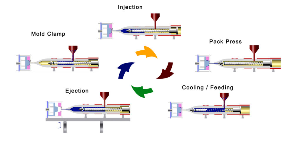
Injection Cycle
The injection molding cycle refers to the complete sequence of events and phases that occur during the production of a molded part using an injection molding machine. The cycle consists of several stages, each with its specific tasks and purposes. It mainly includes mold clamp, injection, pack press, cooling/feeding, and ejection. Other steps that are not very critical will not be discussed for the time being.
Here are a few more professional terms.
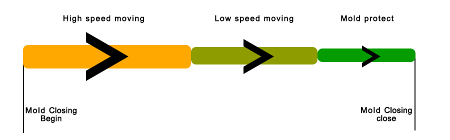
Mold Closing
“Mold closing” is one of the key stages in the injection molding cycle. It refers to the process of closing the two halves of the mold (commonly known as the mold “clamping”) before the injection of molten plastic material. The mold must be securely closed to withstand the pressure of the injected material and ensure the precise formation of the molded part.
The mold closing stage includes the following steps:
- Alignment: The two halves of the mold, which are mounted on the moving and stationary platens of the injection molding machine, are aligned properly.
- Closing: The movable platen, often attached to the moving half of the mold, moves towards the stationary platen, bringing the two mold halves together. The mold is securely closed with the help of a clamping unit.
In actual production, the reason why low-speed movement is required at the moment when the mold is finally closed is because of concerns about mold damage caused by poor mold release or burr of the molded product.
Mold clamping
Mold clamping is a critical stage in the injection molding process that involves securely closing and fastening the two halves of the mold, known as the stationary half (fixed platen) and the moving half (moving platen or ram), to create a sealed cavity for the injection of molten plastic material. [15]
The clamping process is essential for maintaining the structural integrity of the mold and preventing the escape of molten material during injection.
Nozzle Advancing
After the type is closed, it supports the force of the mold in order to prevent the mold from being pushed by the pressure of the flowing resin that allows the Nozzle to occur during injection molding.
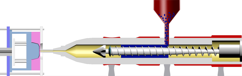
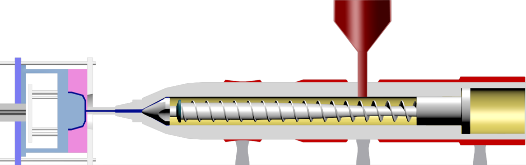
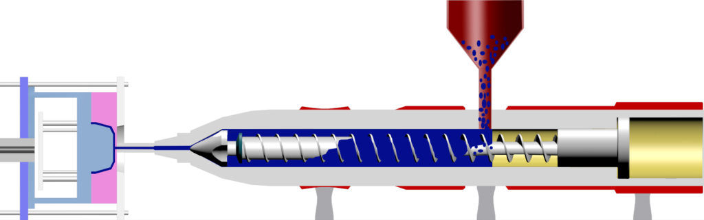
Plasticization
When the resin in the mold undergoes curing, the stage of resin melting starts inside the injection molding machine in preparation for the next Cycle injection. (including the metering stage)
The plastic material is conveyed through a feed throat to the heated barrel of the machine. Inside the barrel, there is a rotating screw that serves several purposes. The heat generated by the barrel and the mechanical energy from the rotating screw work together to melt the plastic material. The melting process converts the solid plastic pellets into a molten state.
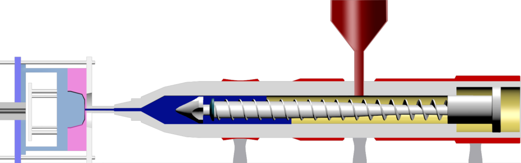
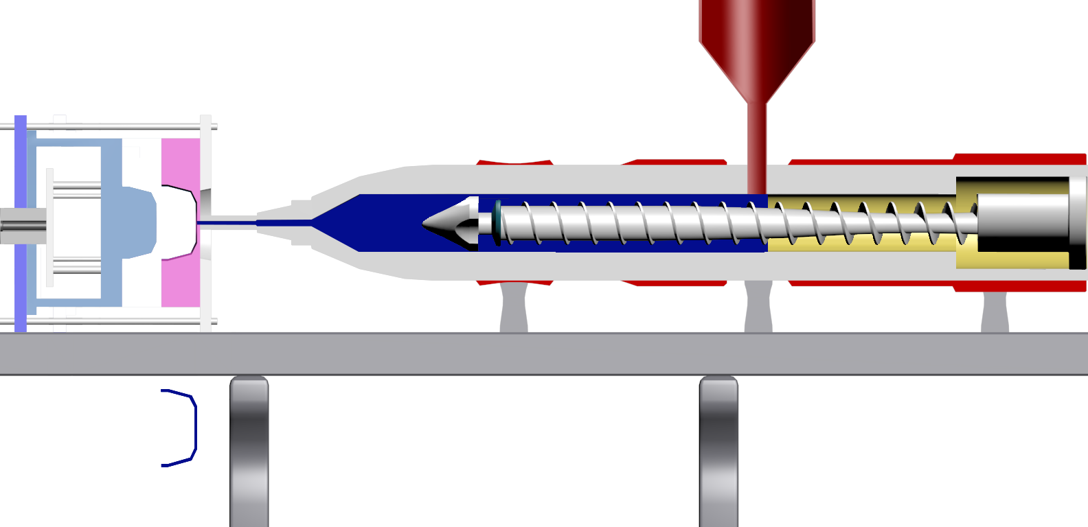
Injection
After the Nozzle and Sprue Bushing are combined, the injection Screw advances forward to supply molten resin into the mold.
Holding
Holding pressure, in the context of injection molding, refers to the pressure that is maintained on the molten plastic material in the mold cavity after the injection phase and before the mold opens. This phase is commonly known as the holding or dwelling phase. Holding pressure is a critical parameter in the injection molding process and serves several important purposes: compensating for shrinkage, preventing sink marks, gate Freeze prevention.
Cooling
In the context of injection molding, “cooling” refers to the stage in the molding cycle where the molten plastic material, which has been injected into the mold cavity and has taken the shape of the desired part, is allowed to cool and solidify. Cooling is a crucial step in the overall injection molding process, and it significantly influences the quality, dimensions, and mechanical properties of the final molded part.
Nozzle Retreat
During the cooling process of the molded resin, in order to prevent nozzle in the resin due to cooling of the mold solidify. The nozzle will retreat, release the contact between the nozzle and the sprue bushing, and prepare for the next injection molding stage. (You can omit it if you don’t have any concerns about nozzle solidification)
It has different functions from Nozzle Advancing.
The specific timing and movement of the nozzle retreat can be programmed and controlled to optimize the injection molding process for the specific requirements of the material and part being produced. Advanced injection molding machines often have features that allow for precise control of the nozzle movement and other parameters, contributing to the production of high-quality molded parts.
Mold Opening & Ejection
After the resin is cured and the mold is opened, the Ejector Pin on the fixed side moves to eject the product from the mold.
Key points regarding the ejection stage in injection molding include ejector pins, ejector system, part design considerations, cycle time optimization, and part handling.
Key points of injection molding conditions
Basics of setting initial molding conditions
1) Temperature: Set as low as possible (for the purpose of preventing decomposition and shortening cycle time)
2) Pressure: Injection pressure, compensation pressure, and back pressure are all set to low (to prevent mold damage caused by OverPacking)
3) packing pressure: Keep the setting high (to prevent Burr and the safety of the equipment)
4) speed
5) Time
When the material cools, it takes a long time, especially during the pressure holding stage, to ensure that the gate is sealed.
Stage injection molding (multi-stage injection molding)
Principle:
- Inject the glue at a low speed for the first injection, move the nozzle to the cold slug head, and then increase the second injection speed to fill the mold cavity to shorten the time for the plastic to flow to the end of the gate, so that the viscosity of the plastic during filling can be maintained to a minimum and solidified. However, it is difficult to control the correct pressure-holding switching point for high-speed injection, so multi-stage deceleration must be used to effectively control the pressure-holding switching point.
- The action principle of segmented injection: the electro-optical control is used to command the flow proportional valve in the hydraulic system to instantly obtain the injection speed at one point to achieve the segmented injection speed.
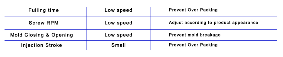
Injection molding speed adjustment method:
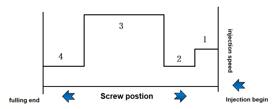
1) Sprue runner section: high speed in the early stage to medium speed in mass production (to prevent solidification & overheating).
2) Glue inlet: low speed (prevent Jetting, Silver Streak, etc.).
3) Molding section: High speed (Prevention of Flow Mark, Weld).
4) Pressure holding part: low speed (Gas, Burr, etc. are reduced, and the switching position of the holding pressure is important).
Injection molding speed function
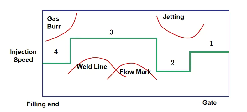
1) To prevent Jetting or Silver Streak around the Gate, it needs to be done at a low speed.
2) To prevent Flow Mark or Weld Line, high speed is required.
3) In order to prevent Gas burning or Burr, medium and low speeds and safe switching are required.
Holding state
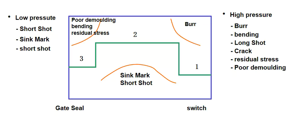
1) To prevent Burr, use low pressure
2) In order to prevent the sink mark or set number from becoming smaller, high voltage is required
3) To prevent residual stress, low pressure is required.
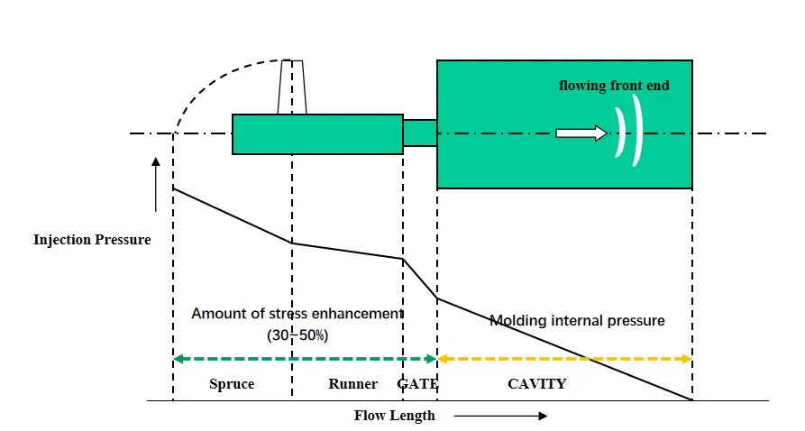
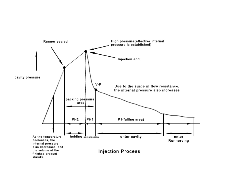
Intra-mold pressure distribution during injection molding process
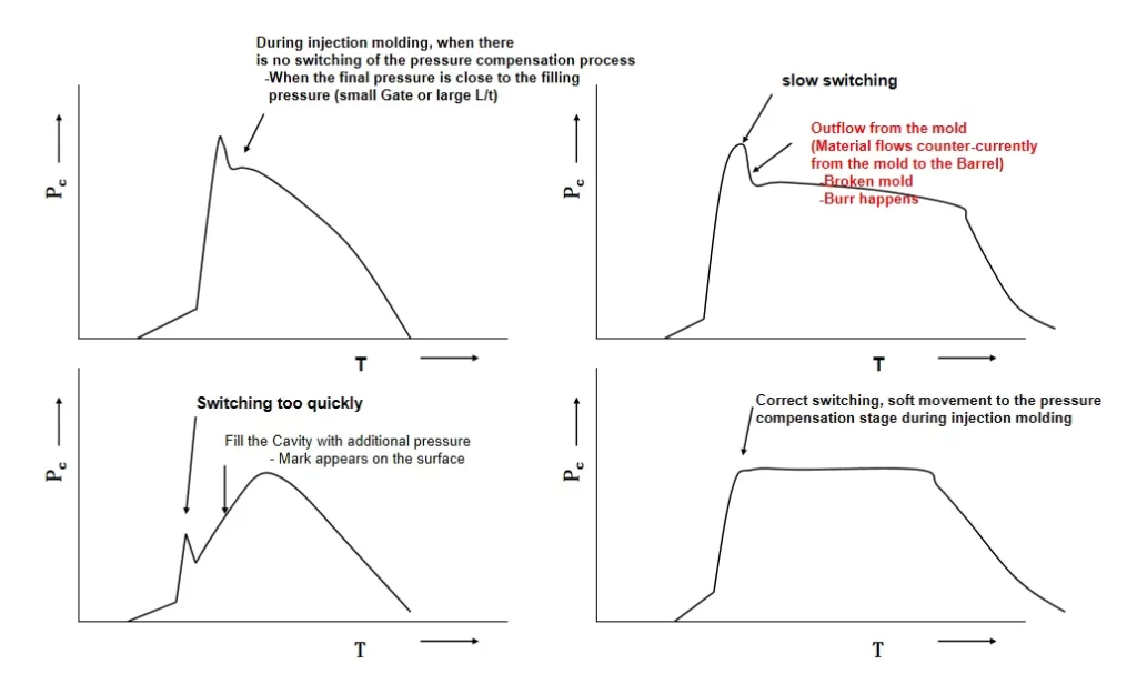
Changes in pressure within the Cavity When V/P Switch
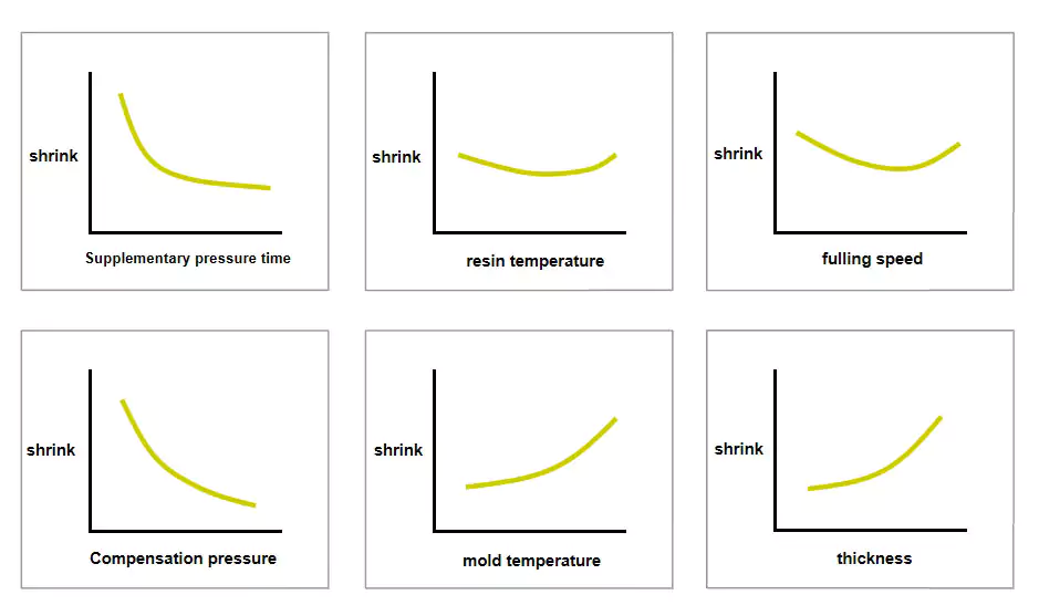
Effect of injection molding conditions on shrinkage rate
Injection molding process optimization:
Through the initial setting conditions of injection molding, shorten the setting time and the number of mold trials.
References:
- [1] Z. Tadmor, Molecular orientation in injection molding, J. Appl. Polym. Sci. 18 (6), pp. 1753–1772, 1974. doi:10.1002/app.1974.07018061
- [2] M. Huszar et al. The influence of flow and thermal properties on injection pressure and cooling time prediction App Math Model (2016)
- [3] P.C. Roozemond et al. Modeling flow-induced crystallization in isotactic polypropylene at high shear rates J Rheol (N Y N Y) (2015)
- [4] O. Ogorodnyk et al. Monitoring and control for thermoplastics injection molding a review Procedia CIRP (2018)
- [5] Pressure Analysis of Dynamic Injection Molding and Process Parameter Optimization for Reducing Warpage of Injection Molded Products Xinyu Wang, Hongxia Li, Junfeng Gu,2 Zheng Li, * Shilun Ruan, Changyu Shen, and Minjie Wang
- [6] Optimize Injection-Molding Process Parameters and Build an Adaptive Process Control System Based on Nozzle Pressure Profile and Clamping Force. Guan-Yan Liou, Wei-Jie Su, Feng-Jung Cheng, Chen-Hsiang Chang, Ren-Ho Tseng, Sheng-Jye Hwang, * Hsin-Shu Peng, and Hsiao-Yeh Chu https://www.ncbi.nlm.nih.gov/pmc/articles/PMC9921389/
- [7] Fast Optimization of Injection Velocity Profile Based on Graph Theory. Peng Zhao,Ding Yang,Huamin Zhou &Kai Xu
- [8] Huang, M.S. Cavity pressure based grey prediction of the filling-to-packing switchover point for injection molding. J. Mater. Process. Technol. 2007, 183, 419–424.
- [9] Huang, M.S.; Nian, S.C.; Chen, J.Y.; Lin, C.Y. Influence of clamping force on tie-bar elongation, mold separation, and part dimensions in injection molding. Precis. Eng. 2018, 51, 647–658.
- [10] Injection Molding Hand book Dominick V. Rosato P.E., Donald V. Rosato PH.D. & Marlene G. Rosato P.E.
- [11] Energy Management in Plastics Processing Strategies, Targets, Techniques, and Tools Book • Third Edition • 2019
- [12] XIONG Wen nan, ZHANG Ya jun, JIN Zhi ming et al., “Research on Energy Consumption of Clamping Process of Injection Molding Machine Based on AMESim [J]”, Plastics, vol. 47, no. 5, pp. 122-125, 2018.
- [13]cientific Method for Determining Cooling Time in Injection Molding Using Infrared Thermography authore: Boud, Eric D
- [14] https://zeus.plmsc.psu.edu/~manias/MatSE447/17-22_Processing.pdf
- [15] What is Clamping Force in Injection Molding | FUTEK https://www.futek.com/applications/Injection-Molding-Force-Feedback
- [2] M. Huszar et al. The influence of flow and thermal properties on injection pressure and cooling time prediction App Math Model (2016)
Basic Guide to Injection Molding Processing by capablemachining is licensed under CC BY-NC 4.0![]()
![]()
![]()