What is CNC macining?
What is CNC machining?
By: CapableMaching
Preface:
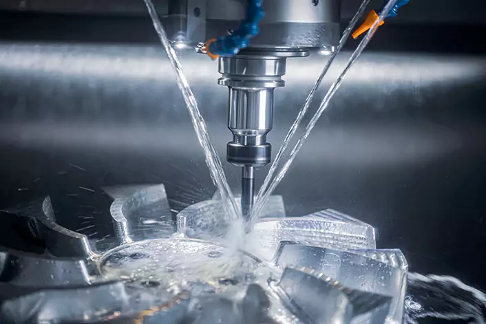
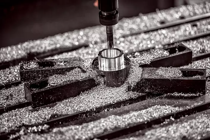
Simply put, it is the use of digital control systems in the processing machine to complete the processing of the entire part. It can complete the machining of many curved surface parts that could not be completed before, and the accuracy and precision of the machining can be well guaranteed.
Introduction
Deep understanding and CNC machining
First, let me explain what CNC is. The full name of CNC is Computer Numerical Control. CNC machining stands for Computer Numerical Control machining. It’s a manufacturing process where pre-programmed computer software dictates the movement of machinery and tools. This process can control a variety of complex machinery, such as grinders, lathes, mills, and routers.
When we start doing CNC machining, we must first formulate the process flow, otherwise we will be plagued by a lot of troubles. If CNC machining processes are not planned, several negative consequences can occur:
- Increased Costs: Without proper planning, CNC machining operations may be inefficient, leading to higher costs associated with wasted materials, increased tooling wear, longer cycle times, and unnecessary downtime.
- Reduced Quality: Without a well-defined machining process plan, there is a higher risk of errors, defects, and inconsistencies in machined parts. This can result in poor quality products that fail to meet customer specifications and requirements.
- Missed Deadlines: Lack of planning can lead to delays in production schedules, missed deadlines, and difficulties in meeting customer demands. This can result in lost opportunities, damaged relationships with customers, and potential financial penalties.
- Safety Hazards: Inadequate planning may lead to safety hazards in the machining environment, such as collisions between cutting tools and workpieces, improper handling of materials, and accidents caused by lack of proper training or supervision.
- Unpredictable Performance: Without a structured process plan, CNC machining operations may suffer from unpredictable performance, variability in output quality, and difficulties in troubleshooting and resolving issues that arise during production.
- Inefficient Resource Utilization: Without proper planning, resources such as machine time, labor, materials, and cutting tools may be underutilized or misallocated, leading to inefficiencies and wasted opportunities for cost savings and productivity improvements.
- Lack of Continuity: Without a consistent process plan, there may be inconsistencies in machining practices, reliance on ad-hoc solutions, and difficulties in maintaining standards and quality control measures across different production runs or shifts.
General CNC machining process
1. Develop processing technology
Developing an efficient CNC machining process involves several key steps, including selecting appropriate cutting tools, determining cutting parameters, optimizing cutting paths, and ensuring overall process reliability. Here’s a guide to developing a CNC machining process:
- Understanding Requirements: Begin by understanding the requirements of the part or product to be machined, including material type, dimensions, tolerances, surface finish, and production volume.
- Material Selection: Choose the appropriate material for the workpiece based on its mechanical properties, machinability, and application requirements.
- Tool Selection: Select cutting tools that are suitable for the material being machined and the desired machining operations. Consider factors such as tool geometry, coating, material composition, and cutting edge geometry. Carbide and high-speed steel are common materials for cutting tools, and various types of tools, such as end mills, drills, reamers, and inserts, may be used depending on the specific machining requirements.
- Cutting Parameters: Determine the optimal cutting parameters, including spindle speed (RPM), feed rate, depth of cut, and cutting speed, based on the material, tooling, machine capabilities, and desired machining results. These parameters should be adjusted to achieve the desired balance between cutting efficiency, tool life, and surface finish.
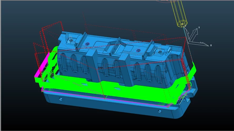
- Toolpath Generation: Use CAM (Computer-Aided Manufacturing) software to generate toolpaths that specify the precise movements of the cutting tool to remove material from the workpiece. Consider factors such as toolpath efficiency, tool engagement, avoidance of collisions, and minimizing unnecessary tool retractions.
- Simulation and Verification: Simulate the machining process using CAM software to verify toolpaths, check for potential collisions, and ensure that the machining operations will produce the desired results without damaging the workpiece or the cutting tools.
- Optimization: Fine-tune the machining process by optimizing cutting parameters, toolpath strategies, and tool selection to improve efficiency, reduce cycle times, and enhance part quality.
- Testing and Validation: Conduct test runs and machining trials to validate the CNC machining process, evaluate the performance of selected cutting tools and parameters, and make any necessary adjustments or refinements.
- Documentation and Standardization: Document the developed CNC machining process, including cutting tool selection, cutting parameters, toolpath strategies, and any specific instructions or considerations. Standardize the process to ensure consistency and repeatability in future machining operations.
- Continuous Improvement: Continuously monitor and analyze the performance of the CNC machining process, gather feedback from operators and machinists, and implement improvements to optimize efficiency, reduce costs, and maintain high-quality standards over time.
2. Convert G-Code
The machining program is the core of CNC machining. It contains information such as machine tool movement instructions, cutting parameters, and cutting paths. Writing processing programs requires the use of CAM (computer-aided manufacturing) software to convert the product’s design files into processing programs, that is, G-code.
When converting a CAD (Computer-Aided Design) file to G-code for CNC machining, several important considerations need attention to ensure accurate and efficient machining operations:
- Geometry Accuracy: Ensure that the CAD model is accurate and free from any errors or inconsistencies. Any inaccuracies or imperfections in the CAD geometry can lead to issues during the machining process and affect the final part dimensions.
- Units and Scaling: Verify that the units used in the CAD file match those expected by the CNC machine. It’s important to correctly scale the CAD model to match the desired dimensions of the final part and to ensure that the G-code generated reflects the correct scaling factor.
- Toolpath Optimization: Optimize the toolpaths generated from the CAD model to minimize machining time, reduce tool wear, and improve surface finish. This involves selecting appropriate cutting strategies, such as roughing, finishing, and contouring, and optimizing toolpath parameters such as feed rates, spindle speeds, and tool engagement.
- Tool Selection and Compensation: Choose the appropriate cutting tools for the machining operations required by the CAD model. Consider factors such as tool geometry, material compatibility, cutting speed, and tool wear. Additionally, implement tool compensation techniques to account for tool deflection and wear during machining.
- Toolpath Verification: Before generating G-code, simulate the toolpaths using CAM (Computer-Aided Manufacturing) software to verify that they are collision-free and produce the desired machining results. This helps identify any potential issues or errors in the toolpaths before they are executed on the CNC machine.
- Post-Processing: Use a post-processor to convert the toolpaths generated by the CAM software into G-code instructions that are compatible with the specific CNC machine being used. Ensure that the post-processor settings are configured correctly to match the capabilities and configuration of the CNC machine.
- Safety Considerations: Pay attention to safety considerations during the CAD to G-code conversion process. Ensure that the toolpaths generated do not pose any safety hazards, such as excessive tool deflection, overloading of the machine, or collisions with fixtures or workpieces.
- Documentation and Version Control: Document the CAD to G-code conversion process, including the settings used, toolpath strategies, and any modifications made to the original CAD model. Maintain version control to track changes and revisions throughout the machining process.
By paying attention to these considerations when converting a CAD file to G-code for CNC machining, manufacturers can ensure accurate, efficient, and reliable machining operations that produce high-quality parts with minimal errors and downtime.
>> How is CNC machining programmed?
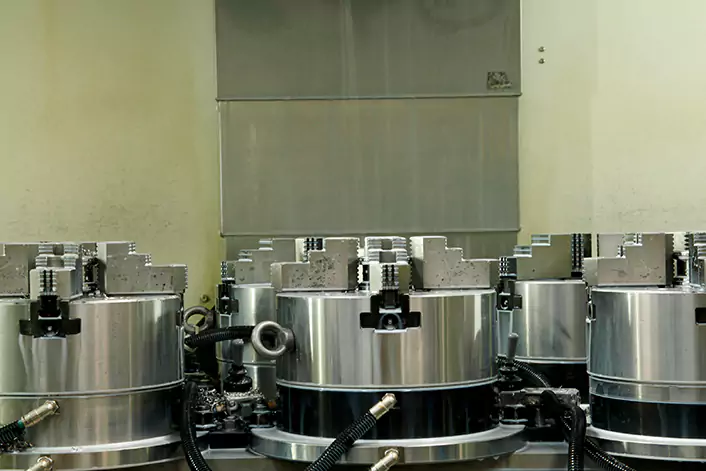
3. Machine tool clamping and tool clamping
Choosing the right workpiece clamping and tool clamping methods is crucial for improving processing accuracy and efficiency in CNC machining. Here are some considerations for selecting appropriate clamping techniques:
Workpiece Clamping:
- a. Fixture Selection: Choose the appropriate type of fixture based on the geometry, size, and material of the workpiece. Options include vices, clamps, fixtures with custom-designed jaws, vacuum chucks, and magnetic chucks.
- b. Stability and Rigidity: Ensure that the workpiece is securely clamped to minimize vibrations, deflection, and distortion during machining. A stable and rigid setup helps maintain accuracy and surface finish and extends tool life.
- c. Accessibility: Consider accessibility to the machining features of the workpiece when selecting clamping methods. Ensure that the chosen clamping solution provides adequate clearance for tool access to all required machining surfaces.
- d. Datum Alignment: Align the workpiece accurately with the CNC machine’s coordinate system and establish proper datum points for consistent and repeatable positioning. This helps ensure accurate machining results across multiple setups and operations.
- e. Flexibility: Choose clamping solutions that offer flexibility to accommodate variations in workpiece size, shape, and orientation. Modular fixtures and adjustable clamping systems allow for quick setup changes and increased versatility.
Tool Clamping:
- a. Tool Holder Selection: Select the appropriate type of tool holder based on the tool shank design, spindle interface, and machining requirements. Common types include collet chucks, hydraulic chucks, milling chucks, and shrink-fit holders.
- b. Runout and Tolerance: Ensure that the tool holder provides minimal runout and high concentricity to maintain accuracy and surface finish during machining. Precision tool holders with low runout contribute to improved tool life and dimensional accuracy.
- c. Balancing: Balance the cutting tool and tool holder assembly to minimize vibrations and improve machining stability. Proper tool balancing reduces tool wear, enhances surface finish, and extends spindle life.
- d. Clamping Force: Apply the appropriate clamping force to securely grip the cutting tool and prevent tool slippage or movement during machining. Avoid over-tightening, which can cause deformation or damage to the tool holder or spindle.
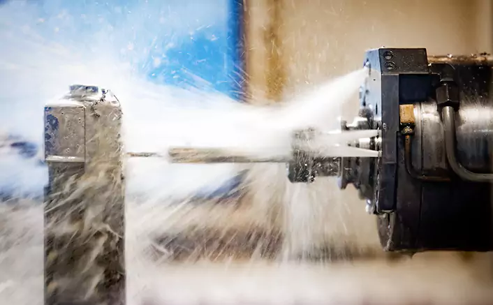
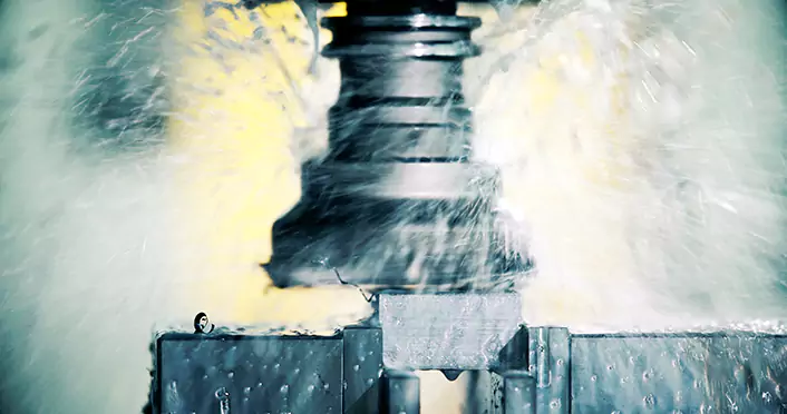
- e. Coolant and Chip Evacuation: Consider the design of the tool holder and clamping system to facilitate efficient coolant delivery and chip evacuation. Proper coolant flow and chip removal help maintain cutting performance and prevent chip buildup.
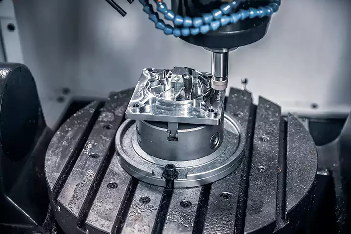
4. Processing operations
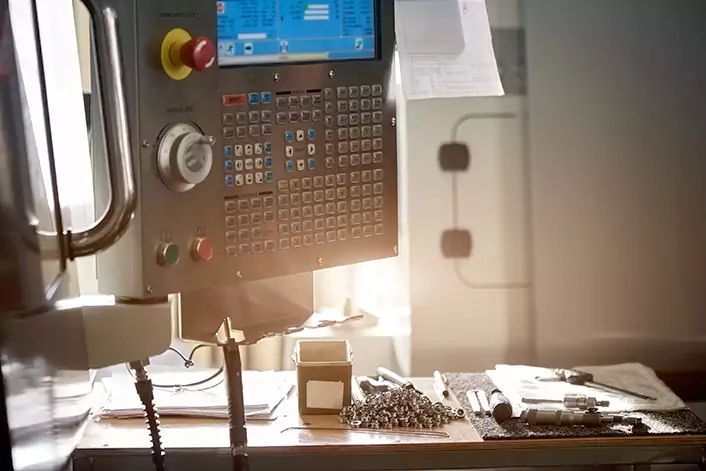
The general factory will have a professional engineer write G-code code, the operator will input the processing program code into the CNC machine tool controller, and then through the controller’s instructions, the machine tool follows the program-specified path and speed of cutting, in the machining process, the operator’s main task is to monitor the machine’s processing status, timely adjustment of cutting parameters, to ensure that the processing of the safety and smooth progress. Here are some key responsibilities and tasks that operators should perform:
- Machine Setup:
- Prepare the CNC machine for operation by ensuring it is clean, lubricated, and in good working condition.
- Load the necessary cutting tools into the tool changer or tool magazine, ensuring they are properly secured and aligned.
- Install the workpiece securely in the machine’s workholding device, such as a vice, chuck, or fixture, using appropriate clamping methods.
- Program Loading:
- Load the CNC program (G-code) into the machine’s control unit from a storage device, network connection, or directly input it using the control panel.
- Verify that the correct program is loaded and review it for any errors or inconsistencies before proceeding.
- Machine Operation:
- Start the CNC machine and initiate the machining process according to the programmed instructions.
- Monitor the machine’s operation, observing tool and workpiece interactions, chip formation, and coolant flow.
- Adjust cutting parameters as needed to optimize machining performance, such as spindle speed, feed rate, and depth of cut.
- Respond to any alarms, warnings, or error messages displayed on the machine’s control panel, troubleshooting issues and taking appropriate corrective actions.
- Quality Control:
- Perform regular inspections of machined parts to ensure they meet the required specifications and quality standards.
- Use precision measuring instruments, such as calipers, micrometers, and gauges, to verify dimensions, tolerances, and surface finish.
- Make adjustments to the machining process as necessary to maintain quality and accuracy, such as tool changes, tool offsets, or program modifications.
- Maintenance and Housekeeping:
- Conduct routine maintenance tasks on the CNC machine, such as cleaning, lubrication, and inspection of components for wear or damage.
- Keep the work area clean and organized, removing chips, debris, and excess coolant to maintain a safe and efficient working environment.
- Report any equipment malfunctions, abnormalities, or safety hazards to supervisors or maintenance personnel for prompt resolution.
- Documentation and Reporting:
- Record production data, including machine runtime, downtime, tool changes, and part counts, as well as any issues or incidents encountered during operation.
- Communicate effectively with supervisors, engineers, and other team members, providing updates on production status, quality issues, and process improvements.
By performing these tasks effectively and attentively, CNC machine operators contribute to the smooth operation of the machining process, ensuring efficient production, high-quality output, and a safe working environment. Ongoing training and skill development are also essential for operators to stay updated on new technologies, techniques, and best practices in CNC machining.
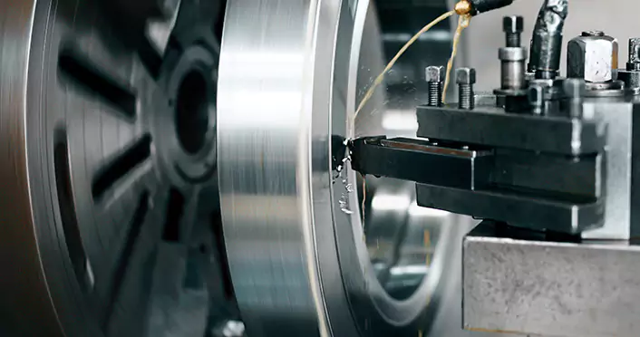
5. Inspection and trimming
Detecting the size, shape, and surface roughness of CNC processed products is crucial for ensuring that they meet the required specifications and quality standards. Various measuring tools and equipment are available for this purpose, each with its specific capabilities and methods. Here are some common equipment and methods used for measuring CNC processed products:
Size and Shape Measurement:
a. Calipers: Used for measuring external dimensions such as length, width, and thickness of machined features. Digital calipers provide precise measurements and may have additional functions such as data output.
b. Micrometers: Ideal for measuring dimensions with higher accuracy, micrometers are used for both external and internal measurements. They are available in various types, including outside micrometers, inside micrometers, and depth micrometers.
c. Height Gauges: Used to measure the height of features or distances between surfaces. They consist of a base, a vertical column, and a measuring probe, and are suitable for measuring flatness and perpendicularity.
d. Coordinate Measuring Machines (CMM): Advanced systems capable of accurately measuring the size, shape, and position of complex features. CMMs use a probe to collect data points on the workpiece surface and generate detailed 3D measurements.
Surface Roughness Measurement:
a. Surface Roughness Testers: Instruments such as profilometers or surface roughness testers are used to quantify the roughness of machined surfaces. They measure parameters such as Ra (average roughness), Rz (average maximum height), and Rt (total height variation).
b. Optical Profilers: These non-contact instruments use optical methods to measure surface roughness and topography with high resolution. They are suitable for measuring complex surfaces and fine features.
c. Scanning Electron Microscopes (SEM): Advanced microscopy techniques used to visualize and measure surface topography at the micro- and nanoscale. SEM provides detailed images and quantitative data on surface roughness and morphology.
d. White Light Interferometers: These instruments use interferometry principles to measure surface roughness by analyzing interference patterns generated by reflected light. They offer high precision and sub-nanometer resolution.
Profile Measurement:
a. Contour Measuring Machines: Used to measure the profile or contour of machined features, such as curves, angles, and complex geometries. These machines typically use laser or optical sensors to capture profile data.
b. Vision Systems: Automated vision systems equipped with cameras and image processing software can measure the profile and dimensions of machined features based on captured images. They are suitable for measuring both 2D and 3D features.
c. Roundness Testers: Specialized equipment used to measure the roundness, cylindricity, and concentricity of cylindrical features. Roundness testers use precision probes or lasers to assess deviations from perfect circularity.
d. Tool Presetters: Used for measuring tool dimensions and profiles before machining operations. Tool presetters ensure that cutting tools are accurately set up and aligned, contributing to dimensional accuracy and surface finish.
By utilizing these measuring tools and equipment, manufacturers can accurately assess the size, shape, surface roughness, and profile of CNC-processed products, ensuring they meet the required specifications and quality standards. Regular calibration and maintenance of measuring equipment are essential to ensure accurate and reliable measurements.
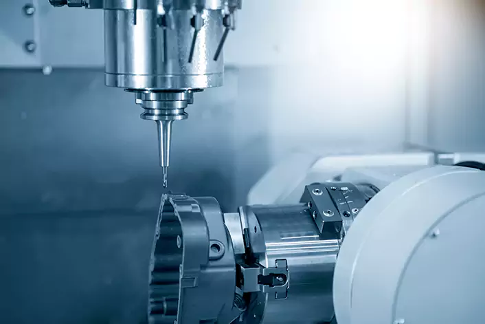
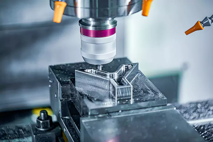
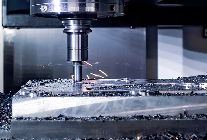
Machine
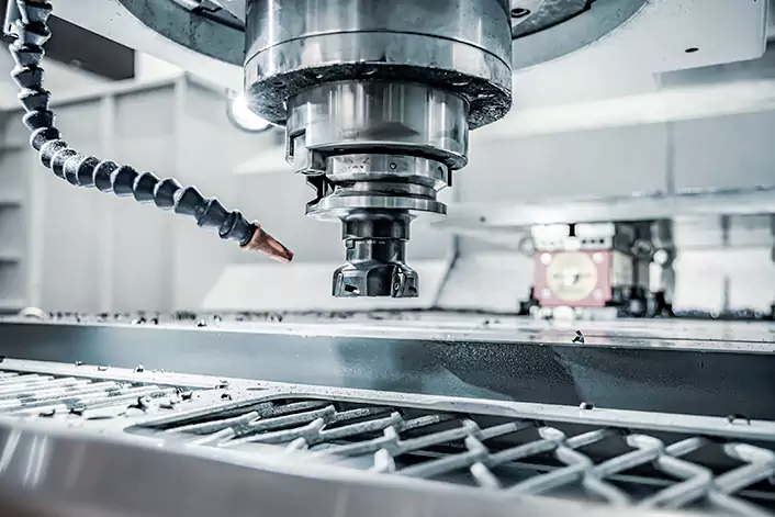
Among all machines with CNC, the CNC milling machine is the most representative. CNC milling is a type of subtractive manufacturing process that uses a computer-controlled machine to remove material from a workpiece. This process involves creating a digital design of the part to be manufactured, which is then loaded into the CNC machine. The machine uses this design to control the movement of the cutting tool, which removes material from the workpiece to create the desired shape.
There are several types of CNC milling machines, including vertical, horizontal, and gantry mills. Each of these machines has its own unique capabilities and advantages, depending on the specific needs of the manufacturer or engineer.
One of the main advantages of CNC machining over traditional methods is the increased precision and accuracy that can be achieved. CNC machines can handle complex geometries and shapes with extreme accuracy, making them ideal for applications where precision is critical.
The advantage of CNC machining is its accuracy, repeatability, and ability to produce complex shapes that would be difficult or impossible to achieve with manual machining methods. It’s widely used in various industries, including automotive, aerospace, electronics, and medical devices, among others.
CNC milling machine is commonly used in industrialized countries around the world, from low-end to high-end, and is used to produce the most modern mechanical processing equipment. In this article, we mainly introduce relevant information related to CNC milling. (The CNC machine mentioned below refers to CNC milling by default)
Types of CNC Machines
There are several types of CNC machines, each with varying levels of complexity and capabilities. The most common types include 3-axis, 4-axis, and 5-axis machines.
3-axis CNC machines are the simplest type and operate on the X, Y, and Z axes. They are commonly used for producing flat or simple curved parts, such as those found in furniture, signage, and electronics.
4-axis CNC machines add the A-axis, or rotational axes, to the three axes of the 3-axis machine. This enables the machine to rotate the part being worked on, allowing for more intricate cuts and contours. This type of machine is commonly used in the aerospace, automotive, and medical industries.
5-axis CNC machines are the most advanced type of CNC machine, adding two rotational axes, typically referred to as the B axis and C axis, to the three axes of the 3-axis machine. This allows for even greater precision and complexity in the production of parts and components. 5-axis machines are commonly used in the aerospace and defense industries, as well as for producing complex medical devices and surgical instruments.
Of these types, the 4-axis CNC machine is a popular choice for manufacturers seeking greater precision and efficiency in their production processes.
Of course, the vertical, horizontal, and gantry mills mentioned above are not commonly used and do not need an important introduction.
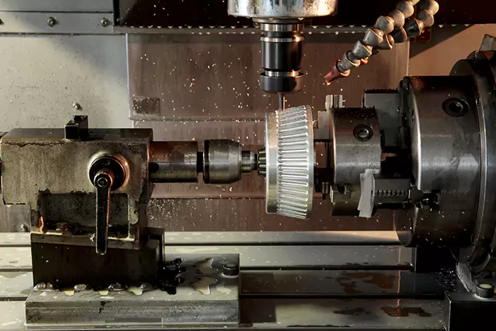
Axes of a Lathe-Milling Compound CNC Machine
Here is a brief introduction lathe-milling compound CNC machine, where the cutting tool post (tool turret or tool magazine) can move up, down, left, and right, possesses processing capabilities similar to a 4-axis CNC milling machine. The spindle for clamping the workpiece can be considered the fourth axis (rotation axis) and has linkage functionality. It’s important to note that while they share similarities, lathe-milling compound CNC machines are not identical to 4-axis CNC milling machines. This is mainly because lathe-milling compound CNC machines typically lack an automatic tool-changing tool magazine, and the power and rigidity of the milling head are not as advanced as those on dedicated CNC milling machines. For more details, you can refer to another blog post we have on this topic.
The fifth axis functionality in lathe-milling compound CNC machines is generally achieved through an additional rotary axis of the tool and usually does not have linkage capabilities. Of course, there are exceptions. High-end lathe-milling compound CNC machines not only feature axis linkage capabilities but also have milling head power comparable to dedicated CNC milling machines. However, such equipment comes at a high cost and is primarily used for the machining of high-value components.
What is 3-axis CNC machining
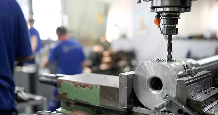
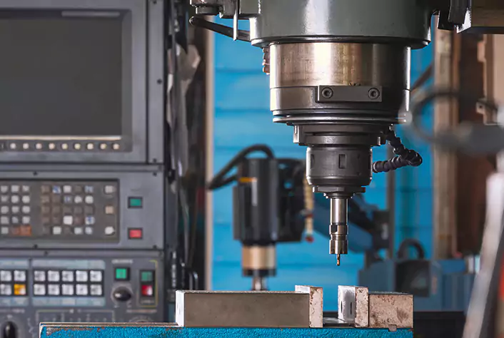
3-axis CNC (computer numerical control) machining is a manufacturing process that uses a computer-controlled cutting tool to remove material from a workpiece. The cutting tool moves in three axes – X, Y, and Z – to create precise cuts and shapes. The X-axis and Y-axis control the horizontal movement of the tool, while the Z-axis controls the vertical movement.
In 3-axis CNC machining, the cutting tool remains perpendicular to the surface of the workpiece throughout the process. This limits the complexity of the shapes that can be produced but allows for relatively fast and straightforward manufacturing of simple parts with straight sharp edges and flat surfaces.
3-axis CNC machining is commonly used in a variety of industries, including aerospace, automotive, electronics, and medical devices. It is ideal for producing simple parts such as brackets, panels, and housings, and is often used for prototyping and small-scale production runs.
Components of a 3-axis CNC milling machine
A 3-axis CNC milling machine consists of several key components that work together to create precise and accurate parts and components. Some of the main components of a 3-axis CNC milling machine include:
1. Machine frame: This is the backbone of the machine that provides the necessary stability and rigidity for the machining process.
2. Spindle: The spindle is the motorized tool that rotates the cutting tool or drill bit. It is responsible for creating the cutting action needed to shape the material being machined.
3. Worktable: The worktable is the surface on which the material being machined is placed. It can move along the X and Y axes to allow for precise positioning of the material.
4. CNC controller: The CNC controller is the brain of the machine, responsible for interpreting the CAD/CAM software and controlling the movement of the machine along the X, Y, and Z axis.
5. Cutting tools: Cutting tools are the various tools used in the machining process, such as end mills, drills, and reamers. These tools are selected based on the specific material being machined and the desired shape or finish.
Together, these mechanical components work in sync to produce highly precise and accurate parts and components, making 3-axis CNC machining a critical technology in the manufacturing industry.
How 3-axis CNC machining works
3-axis CNC machining involves several steps, from the design of the part in CAD software to the actual machining process. Here’s how it works:
1. Computer-aided design (CAD) and computer-aided manufacturing (CAM): The first step in 3-axis CNC machining is designing the part in CAD software. Once the design is complete, it is converted to a format that can be read by the CAM software.
2. Generating G-code: The CAM software generates G-code, which is a series of commands that the CNC machine can understand. The G-code contains information on the tool path, speed, and depth of cut.
3. Loading the G-code into the CNC controller: The G-code is loaded into the CNC controller, which is responsible for interpreting the code and controlling the movement of the machine.
4. Setting up the machine: The workpiece is loaded onto the worktable and secured in place. The cutting tool is also installed and secured in the spindle.
5. Executing the program: Once the machine is set up, the program is executed. The CNC controller reads the G-code and moves the machine along the X, Y, and Z axis to create the desired shape.
6. Post-processing and inspection: After the machining process is complete, the part is inspected for accuracy, and any necessary post-processing steps are performed.
Applications of 3-axis CNC machining
3-axis CNC milling is a manufacturing process that uses a computer-controlled cutting tool to remove material from a workpiece. The tool moves in three axes (X, Y, and Z) to create precise cuts and shapes. Here are some common applications of 3-axis CNC milling:
1. Prototyping: 3-axis CNC milling is often used to create prototypes of new products. It can produce precise and accurate parts quickly, allowing designers to test and refine their ideas before moving into production.
2. Aerospace and Defense: 3-axis CNC milling is used extensively in the aerospace and defense industries to create complex parts for aircraft, missiles, and other vehicles. These parts must meet strict tolerances and quality standards, and 3-axis CNC milling is ideal for producing them.
3. Automotive: The automotive industry uses 3-axis CNC milling to create parts for engines, transmissions, suspension systems, and more. This process allows for high levels of precision and accuracy, which is essential in automotive manufacturing.
4. Medical Devices: The medical industry uses 3-axis CNC milling to create implants, prosthetics, and other medical devices. These parts must be highly precise and customized to fit the needs of individual patients.
5. Jewelry: 3-axis CNC milling is used in the jewelry industry to create intricate designs and patterns on metal, such as rings, pendants, and bracelets.
6. Electronics: The electronics industry uses 3-axis CNC milling to create printed circuit boards (PCBs) and other components. This process allows for the precise and accurate manufacturing of small, intricate parts.
7. Mold Making: 3-axis CNC milling is used in mold making to create molds for plastic injection molding, die casting, and other manufacturing processes. This allows for the mass production of parts with greater accuracy and consistency.
Advantages of 3-axis CNC machining
3-axis CNC machining offers several advantages over traditional machining methods. Some of the key advantages include:
1. High accuracy and repeatability: 3-axis CNC milling machines can produce highly accurate parts with tight tolerances, which ensures consistency and repeatability in production runs.
2. High production speed: CNC machines can operate continuously without the need for manual intervention, which means they can produce parts at a much faster rate than traditional machining methods.
3. Ability to machine complex shapes: CNC machines can machine complex shapes with ease, including parts with intricate geometries and curved surfaces.
4. Reduced labor costs: CNC machines require minimal manual labor, which can significantly reduce labor costs and increase efficiency in production processes.
In general, 3-axis CNC milling is a versatile and efficient process that offers numerous benefits over traditional machining methods. It has become a widely used technology in various industries, including automotive, aerospace, medical, and electronics, among others.
Limitations of 3-axis CNC machining
Despite the numerous advantages of 3-axis CNC machining, there are also some limitations to this technology. Some of the key limitations include:
1. Limited range of motion: the 3-axis CNC milling machine can only move along three axes (X, Y, and Z), which limits its ability to machine complex parts with features on multiple sides.
2. Limited ability to machine undercuts or features on multiple sides of a part: the 3-axis CNC milling machine can only machine features that are accessible from above, which limits its ability to machine undercuts or features on multiple sides of a part.
3. Requires skilled operators: The 3-axis CNC milling machine requires skilled operators who have experience with the programming, setup, and operation of the machine. This can lead to higher labor costs and long setup times.
While 3-axis CNC machining is a highly efficient and versatile technology, it does have some limitations that must be taken into account when selecting a machining method for a particular application. For more complex parts, 4 or 5-axis CNC machining may be a better option.
How to Find a High Precision 3-Axis CNC Machining Services Provider
First, identify your specific needs. Before you begin your search, it’s important to identify your specific requirements for your parts or products. Determine the material, tolerances, and surface finish requirements for your parts.
Once you have defined your needs, you should start looking for a high-precision 3-axis CNC machining service provider. Capable Machining is your reliable choice. They specialize in providing the highest quality CNC machining services to meet the needs of clients worldwide.
1. Precision: Capable Machining is known for providing precision machining services using advanced 3-axis CNC milling machines. This ensures that every component produced meets strict quality standards and tolerances.
2. Versatility: Capable Machining has the ability to machine a wide range of materials, including metals, plastics, and composites. This allows them to provide machining services for a variety of industries, such as aerospace, medical, and automotive.
3. Efficiency: Capable Machining utilizes advanced CNC machining technology and software to optimize production processes and reduce lead times. This ensures that customers receive their components in a timely and cost-effective manner, without compromising on quality.
Final Thoughts
In conclusion, 3-axis CNC machining is a highly efficient and versatile manufacturing technology that offers several advantages over traditional machining methods. It is widely used in various industries, including automotive, aerospace, medical, and electronics, among others.
One of the key advantages of 3-axis CNC machining is its high accuracy and repeatability, which ensures consistent and reliable production runs. It also offers high production speed and the ability to machine complex shapes with ease, making it ideal for a wide range of applications.
However, there are also some limitations to 3-axis CNC machining, including its limited range of motion and ability to machine undercuts or features on multiple sides of a part. It also requires skilled operators who have experience with the programming, setup, and operation of the machines.
Overall, 3-axis CNC machining is a valuable technology that has transformed the manufacturing industry. By understanding its advantages and limitations, manufacturers can determine when and where to best apply this technology in their operations.
What is 4-axis CNC Machining?
CNC machining, or computer numerical control machining, is a modern manufacturing process that uses automated machinery and computer programming to create precise and complex parts and components. One type of CNC machining is 4-axis machining, which adds an additional rotary axis to the more commonly used 3-axis machines.
4-axis CNC machining allows for greater precision and versatility in the production of complex parts. The fourth axis, also known as the A-axis, enables the machine to rotate the part being worked on, allowing for more intricate cuts and contours.
With 4-axis CNC machining, manufacturers can produce highly detailed and accurate parts with greater efficiency and precision than with traditional machining methods.
How 4-axis CNC Machining Works
4-axis CNC machining works by adding a rotary axis, known as the A-axis, to the traditional X, Y, and Z axis. The A-axis allows the machine to rotate the part being worked on, which adds greater precision and flexibility to the manufacturing process.
Axis movement
The X, Y, and Z axis control the movement of the cutting tool, while the A axis controls the rotation of the part being worked on. This allows for more intricate cuts and contours to be made with greater precision.
Tools used in 4-axis CNC machining
4-axis CNC machines use a range of cutting tools, including drills, end mills, and reamers. These tools are used to remove material from the workpiece and create the desired shape and design.
4-axis CNC machining process
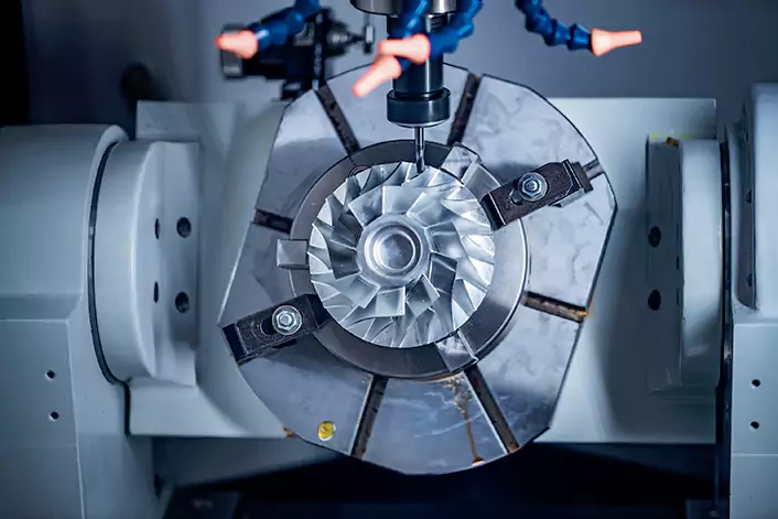
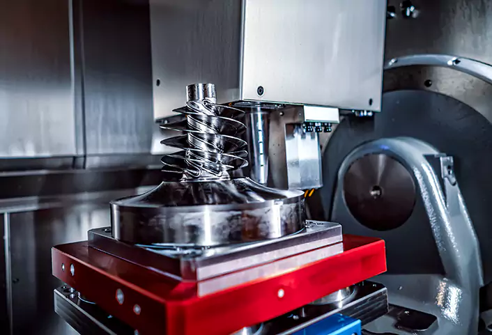
An example of a 4-axis CNC machining process would be the production of a complex metal part, such as a turbine blade. The part would be mounted on the machine’s rotary table, which is controlled by the A-axis. The cutting tool would then move along the X, Y, and Z axis to remove material from the workpiece, while the rotary table rotates the part to create the desired shape and contour.
In a word, 4-axis CNC machines are capable of producing highly accurate and detailed parts with greater efficiency and precision than traditional machining methods.
Materials machined with a 4-axis CNC machine
A 4-axis CNC machine can machine all the materials that a 3-axis machine can handle, plus it adds the ability to machine more complex parts that require rotation around a 4th axis. This additional axis provides more flexibility and control to the machining process. Some examples of materials that can be machined with a 4-axis CNC machine are:
- Wood: Such as hardwoods, softwoods, MDF, and plywood.
- Plastics: Such as nylon, polystyrene, and polypropylene.
- Metals: Such as aluminum, brass, copper, stainless steel, and titanium.
- Composites: Such as carbon fiber, fiberglass, and Kevlar.
- Foam: Such as polystyrene foam and polyurethane foam.
- Ceramics: Such as porcelain, alumina, and zirconia.
Benefits of 4-axis CNC Machining
There are several benefits to using 4-axis CNC machining for manufacturing parts and components, including:
Increased precision
4-axis CNC machines offer greater precision than traditional machining methods, as they are able to produce more intricate cuts and contours with greater accuracy. This results in higher-quality parts that meet tighter tolerances.
Faster production times
4-axis CNC machines are able to produce parts faster than traditional machining methods, as they are able to make multiple cuts at once and can work on multiple sides of a part without the need for manual intervention. This results in faster turnaround times and increased productivity.
More complex designs possible
4-axis CNC machines enable manufacturers to produce more complex parts and components that would be difficult or impossible to create with traditional machining methods. This opens up new possibilities for product design and innovation, particularly in industries such as aerospace and medical device manufacturing.
Overall, 4-axis CNC machining offers a range of benefits for manufacturers seeking greater precision, efficiency, and design flexibility in their production processes. As technology continues to advance, it is likely that the use of the 4-axis and other types of CNC machines will become even more widespread in the manufacturing industry.
Applications of 4-axis CNC Machining
4-axis CNC machining has a wide range of applications in various industries, including:
Aerospace industry
The aerospace industry relies heavily on 4-axis CNC machining for the production of complex parts and components for aircraft, such as turbine blades, engine components, and structural parts. The high precision and accuracy of 4-axis CNC machines make them an ideal choice for the demanding requirements of aerospace manufacturing.
Automotive industry
The automotive industry also uses 4-axis CNC machines for the production of complex parts and components, such as engine blocks, transmission components, and suspension parts. The high efficiency and precision of 4-axis CNC machines allow for faster production times and improved part quality.
Medical industry
In the medical industry, 4-axis CNC machines are used to produce complex surgical instruments and medical devices, such as implants and prosthetics. The precision and accuracy of 4-axis CNC machines are critical in the manufacturing of these types of products, as they must meet strict safety and quality standards.
Jewelry industry
The jewelry industry also utilizes 4-axis CNC machines for the production of intricate and detailed designs in metals and other materials. The precision and flexibility of 4-axis CNC machines allow for the creation of unique and complex designs that would be difficult or impossible to achieve with traditional jewelry-making techniques.
Generally speaking, 4-axis CNC machining has a wide range of applications in various industries, from aerospace and automotive manufacturing to medical device and jewelry production. The versatility and precision of 4-axis CNC machines make them an essential tool for modern manufacturing processes.
Factors to Consider When Choosing 4-Axis Milling
When considering 4-axis milling as a machining method, there are several factors that must be taken into account to ensure that it is the best option for the specific project. Here are some of the most important factors to consider when choosing 4-axis milling:
Cost
Cost is always an important factor when choosing a machining method. 4-axis milling is generally more expensive than 3-axis milling, but less expensive than 5-axis milling. The cost of the machine and the labor required to operate it are both factors to consider when deciding whether 4-axis milling is feasible.
Material Properties
Different materials have different properties that can affect the machining process. For example, some materials may be more difficult to machine than others or may require different cutting tools or machining parameters. The material properties must be considered when selecting the appropriate machining method, as well as the tooling and cutting parameters.
Complexity of Part Design
4-axis milling is a good choice for parts with complex geometries, but it is important to consider the specific requirements of the part when selecting a machining method. If the part requires multiple setups or special fixturing, 4-axis milling may not be the best option. On the other hand, if the part has features that can be accessed more easily with a fourth axis, such as holes or pockets on the side of a part, 4-axis milling can be a very efficient option.
Required Tolerances
Tolerances are the allowable variation in a dimension or feature on a part. Depending on the required tolerances, 4-axis milling may or may not be the best option. 4-axis milling can achieve high levels of accuracy and precision, but may not be as precise as 5-axis milling in certain situations.
When choosing 4-axis milling, it is important to consider the cost, material properties, complexity of part design, and required tolerances. By taking these factors into account, manufacturers can make informed decisions about the best machining method for their specific project.
Final Thoughts
In conclusion, 4-axis CNC machining offers a range of benefits for manufacturers seeking greater precision, efficiency, and design flexibility in their production processes. By adding a rotating axis, the A-axis, to the traditional X, Y, and Z axes, 4-axis CNC machines can produce more intricate cuts and contours with greater accuracy, resulting in higher quality parts that meet tighter tolerances.
The benefits of 4-axis CNC machining include increased precision, faster production times, and the ability to produce more complex designs, making it an ideal choice for a wide range of industries. From aerospace and automotive manufacturing to medical device and jewelry production, 4-axis CNC machines are an essential tool for modern manufacturing processes.
Overall, 4-axis CNC machining offers manufacturers a highly efficient and precise method of production that allows for greater flexibility and innovation in product design. As technology continues to advance, it is likely that the use of the 4-axis and other types of CNC machines will become even more widespread in the manufacturing industry.
What is 5-axis CNC milling
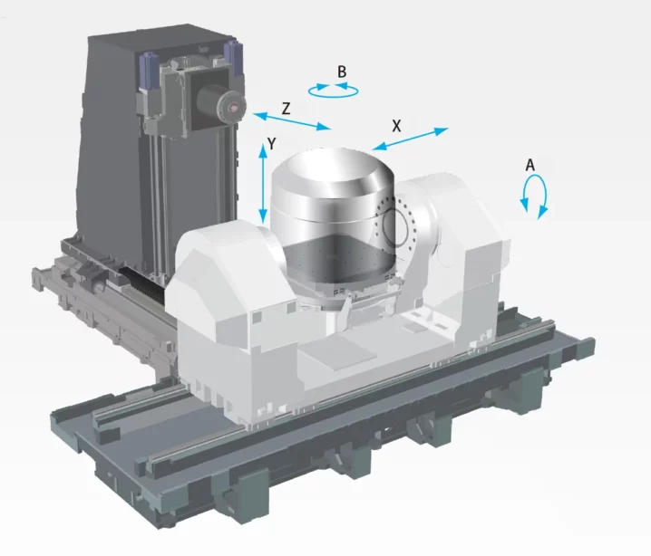
5-axis CNC milling is a machining process where a computer-controlled machine tool removes material from a workpiece using rotary cutters in multiple directions simultaneously. Unlike traditional 3-axis milling, which moves the cutting tool in three linear axes (X, Y, and Z), 5-axis milling allows for additional rotation around two more axes, typically referred to as A and B axes.
With 5-axis CNC milling, the cutting tool can move along the X, Y, and Z axes while also tilting or rotating along the A and B axes. This capability enables the machine to approach the workpiece from multiple angles, allowing for more complex geometries and intricate cuts to be made with a single setup.
5-axis CNC milling is commonly used in industries such as aerospace, automotive, medical, and mold making, where precision and intricate shapes are required. It offers advantages such as reduced setup times, improved surface finish, and the ability to machine complex parts in fewer operations.
Understanding the Axes System
In CNC machining, the axes system is used to define the motion of the cutting tool relative to the workpiece. This system consists of several axes that control the movement of the CNC machine in different directions.
The most common axes system used in CNC milling is the XYZABC system, referring to two horizontal axes, two rotational axes, and one vertical, where:
● X-axis: Horizontal movement from left to right
● Y-axis: Horizontal movement from front to back
● Z-axis: Vertical movement up and down
● A-axis: Rotational movement around the X-axis
● B-axis: Rotational movement around the Y-axis
● C-axis: Rotational movement around the Z-axis
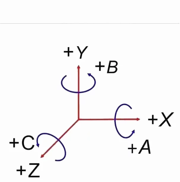
This system allows the cutting tool to move in six different directions, allowing for complex cuts and contours.
Another way of defining the axes system is the UVW system, which is commonly used in 5-axis CNC machining. In this system, the U, V, and W axes are defined as follows:
● U-axis: Parallel to the X-axis
● V-axis: Parallel to the Y-axis
● W-axis: Parallel to the Z-axis
These axes are used to control the orientation of the workpiece relative to the cutting tool, allowing for greater flexibility in the machining process.
How 5-axis CNC Milling Works
5-axis CNC mills differ from 3-axis or 4-axis machines in that they have an additional rotational axe (A or B) that allows for more complex and intricate cuts. This axis tool rotates the workpiece or cutting tool around a fixed axis, allowing for cuts and contours at various angles and orientations.
The advantages of 5-axis CNC milling
1. Greater flexibility – With an additional axis, the 5-axis CNC mill can create more complex and intricate parts with ease. This flexibility allows manufacturers to create parts with more complex geometries and designs.
2. Improved efficiency – 5-axis CNC mill can significantly reduce the time and labor required for part setup, as it allows for multiple cuts and contours to be made in a single setup.
3. Improved accuracy – By allowing for cuts at various angles and orientations, a 5-axis CNC mill can increase accuracy and surface quality.
Applications of 5-axis CNC milling
1. Aerospace – 5-axis CNC machining is commonly used in the aerospace industry for the production of intricate parts, such as engine components and wing sections.
2. Medical – Medical device manufacturers use 5-axis CNC machining to produce complex and intricate parts, such as surgical implants and prosthetics.
3. Automotive – 5-axis CNC machining is used in the automotive industry for the production of complex parts, such as engine blocks and transmission components.
4. Mold and die making – 5-axis CNC machining is used in mold and die making for the production of complex shapes and geometries, such as injection molds and die-cast dies.
5-axis CNC milling is an advanced high-speed machining technology that allows for complex and intricate cuts and contours. With its additional axes, 5-axis CNC milling offers greater flexibility, improved efficiency, and improved accuracy, making it a popular choice for different industries, including aerospace, medical, automotive, and mold and die-making.
Tools and Machines Used in 5-axis CNC Milling
To achieve the precision and accuracy required for 5-axis CNC machining, specialized tools, and machines are required. Here are the tools, machines, and software typically used in 5-axis CNC machining:
Tools and Cutters Used in 5-axis CNC Milling
The shorter cutting tools used in 5-axis CNC milling are typically high-speed steel or carbide tools. These tools come in a variety of shapes and sizes to allow for the creation of a wide range of shapes and geometries.
Some of the most common types of cutting tools used in 5-axis CNC milling include ball end mills, the bull nose end mills, and tapered end mills. Each of these tools has its own unique shape and cutting profile, allowing for the creation of highly specific geometries.
Types of Machines Used in 5-axis CNC Milling
There are several types of machines used in 5-axis CNC machining, each with its own unique capabilities and advantages. Some of the most common types of machines used in 5-axis CNC machining include:
1. Vertical Machining Centers (VMCs) – VMCs are some of the most common types of 5-axis CNC machines. They are typically used for cutting small to medium-sized parts and are known for their versatility and flexibility.
2. Horizontal Machining Centers (HMCs) – HMCs are similar to VMCs but are designed for cutting larger parts. They are often used in industries such as aerospace and automotive manufacturing.
3. Gantry Mills – Gantry mills are large, heavy-duty machines that are capable of cutting very large parts. They are often used in the production of molds, dies, and other large components.
Software Used in 5-axis CNC Milling
In addition to specialized machines and cutting tools, the software is also a critical component of 5-axis CNC milling. This software is used to create digital designs that are loaded into the CNC machine to control the cutting process.
Some of the most common software programs used in 5-axis CNC milling include:
1. Computer-Aided Design (CAD) software – CAD design software is used to create digital designs that are loaded into the CNC machine.
2. Computer-Aided Manufacturing (CAM) software – CAM software is used to generate the tool paths that the cutting tool will follow to create the desired shape.
3. Simulation software – Simulation software is used to test and optimize the cutting process before the actual machining takes place.
Benefits and Limitations of 5-axis Milling
5-axis CNC milling has several benefits that make it an attractive option for many manufacturers and engineers. However, there are also some limitations that need to be considered before deciding to invest in this technology.
Benefits of 5-axis CNC Milling
1. Precise cuts – 5-axis CNC milling allows for extremely precise cuts and contours, resulting in parts with high accuracy and surface finish quality.
2. Reduced setup time – The ability to cut complex geometries in a single setup reduces the time and labor required for part setup, resulting in increased efficiency and productivity.
3. Versatility – 5-axis CNC machines can produce a wide variety of parts and components, from small and intricate to large and complex.
4. Reduced scrap – With its high precision and accuracy, 5-axis CNC milling can significantly reduce scrap and waste material, resulting in cost savings and environmental benefits.
5. Reduced lead time – By eliminating the need for multiple setups and reducing scrap, 5-axis CNC milling can shorter lead times and improve turnaround times for parts production.
Limitations of 5-axis CNC Milling
1. Cost – 5-axis CNC machines are typically more expensive than 3-axis or 4-axis machines, which can be a significant investment for smaller manufacturers or businesses.
2. Complexity – 5-axis CNC machines require specialized training and expertise to operate and program, which can be a challenge for some businesses.
3. Maintenance – 5-axis CNC machines require regular maintenance and upkeep to ensure optimal performance and longevity.
4. Size limitations – While 5-axis CNC machines are capable of producing large parts, there are still size limitations depending on the specific machine and application.
5. Software limitations – While the software is critical for 5-axis CNC milling, there are limitations in the software’s ability to create complex geometries or handle large data sets, which can impact the machine’s performance.
Generally speaking, 5-axis CNC milling offers numerous benefits, including high precision and accuracy, reduced setup time, versatility, and reduced scrap. However, there are also some limitations to consider, such as cost, complexity, maintenance requirements, size limitations, and software limitations. Careful consideration of these factors is necessary to determine if 5-axis CNC milling is the right choice for a particular manufacturing or engineering application.
Future of 5-axis CNC Milling
As with most advanced technologies, the future of 5-axis CNC milling is likely to see continued evolution and innovation. In recent years, there have been several developments that suggest a bright future for this technology.
One potential area of advancement is in the software used to control the 5-axis CNC machine. As computer technology continues to improve, software developers are finding new ways to improve the accuracy, speed, and efficiency of these machines. This includes the use of advanced algorithms, machine learning, and artificial intelligence to optimize the milling process and reduce errors.
Another potential area of advancement is in the hardware used in 5-axis CNC milling. For example, there has been an increase in the use of hybrid additive-subtractive manufacturing, where 3D printing technology is integrated with 5-axis CNC milling to create highly complex and intricate parts. This approach combines the benefits of both technologies, allowing for greater flexibility, precision, and speed.
Additionally, advancements in materials science are also likely to impact the future of 5-axis CNC milling. As new materials are developed that are more difficult to machine with traditional methods, 5-axis CNC milling machines will become even more important for the production of intricate parts and components.
The future of 5-axis CNC milling is likely to see continued evolution and innovation, driven by advancements in software, hardware, and materials science. As this technology becomes more advanced and sophisticated, it will continue to play a critical role in the manufacturing and engineering industries, enabling the production of highly complex and intricate parts with greater precision, speed, and efficiency.
Conclusion
5-axis CNC milling has become an essential technology in the manufacturing and engineering industries. With its ability to create complex and intricate cuts and contours with precision, accuracy, and efficiency, it has revolutionized the way that many industries produce parts and components. From aerospace and medical to automotive and mold and die making, 5-axis CNC milling has played a critical role in shaping the modern manufacturing industry.
In addition to its current importance, the future of 5-axis machining looks bright, with continued advancements and innovations likely to make this technology even more essential in the years to come. As computer technology, materials science, and hardware continue to evolve, 5-axis CNC machines will become even more sophisticated, efficient, and precise, enabling manufacturers to create increasingly complex and intricate parts with ease.
In conclusion, 5-axis machining has changed the way that we think about manufacturing, and it will continue to shape the industry for many years to come. Its importance cannot be overstated, and it will remain a critical technology for the production of high-quality parts and components.
Differences between 3-axis milling, 4-axis milling, and 5-axis milling
The main differences between 3-axis, 4-axis, and 5-axis milling are the number of axes that the cutting tool can move along, the complexity of the parts that can be produced, and the level of precision that can be achieved. Here are the key differences between these three types of milling:

1. 3-axis milling: In 3-axis milling, the cutting tool can move along the X, Y, and Z axes. This is the most basic type of milling and is suitable for producing simple, flat parts with relatively straight edges. However, it is limited in its ability to produce complex shapes and curves.
2. 4-axis milling: In 4-axis milling, the cutting tool can move along the X, Y, and Z axes as well as an additional rotational axis. This allows for more complex parts to be produced, such as parts with curved surfaces or angled features. 4-axis milling is commonly used in industries such as aerospace and automotive, where parts with complex shapes and angles are required.
3. 5-axis milling: In 5-axis milling, the cutting tool can move along the X, Y, and Z axes as well as two additional rotational axes. This allows for even greater complexity in the parts that can be produced, including parts with highly contoured surfaces and intricate details. 5-axis milling is commonly used in industries such as medical, dental, and jewelry, where highly detailed and precise parts are required.
Generally speaking, the key advantages of 4-axis and 5-axis milling over 3-axis milling are the ability to produce more complex shapes, achieve higher levels of precision, and reduce the need for multiple setups and operations. However, these advantages also come with increased costs, as 4-axis and 5-axis milling machines are typically more expensive than 3-axis CNC milling machines and require more Offersskilled operators to run.
Comparison
3-Axis Milling vs 4-axis milling:
3-axis milling is a simpler form of CNC milling that involves the cutting tool moving along three axes – X Y Z. While 3-axis milling can produce basic shapes and designs, it has limited capabilities when it comes to producing complex parts with curved surfaces or undercuts. It also requires more setups, which can increase production time and costs. On the other hand, 4-axis milling adds a fourth axis of rotation to the cutting tool, allowing it to machine parts with more complex geometries and features. With the fourth axis, the tool can move around the part, allowing for better access to all sides of the part and reducing the need for multiple setups. This leads to faster production times and increased accuracy and precision.
5-Axis Milling vs 4-axis milling:
5-axis milling is the most advanced type of milling, adding two additional axes of rotation to the cutting tool. This allows for even more complex geometries and the ability to produce parts with undercuts and deep pockets. However, 5-axis milling is more expensive and requires more advanced programming and machining skills, making it less accessible to some manufacturers. 4-axis milling offers a good compromise between simplicity and complexity, with the ability to produce more complex parts faster and with greater accuracy than 3-axis milling.
While 3-axis milling is a simpler and less expensive method, it has limited capabilities when it comes to producing complex parts. 4-axis milling offers a good compromise between simplicity and complexity, with the ability to produce more complex parts faster and with greater accuracy than 3-axis milling. 5-axis milling is the most advanced option but comes with higher costs and more specialized requirements. Ultimately, the choice between these methods will depend on the specific needs of the project and the capabilities of the manufacturer.
When is 4- or 5-axis milling preferred to 3-axis milling?
In general, the unit cost per machining time is lower for 3-axis CNC machining compared to 4-axis milling, and 4-axis milling is generally more cost-effective than 5-axis milling. Therefore, if the machining time is similar, prioritizing 3-axis CNC machining over 4-axis or 5-axis CNC machining is preferable. The use of 4-axis or 5-axis CNC machining is warranted in only three situations.
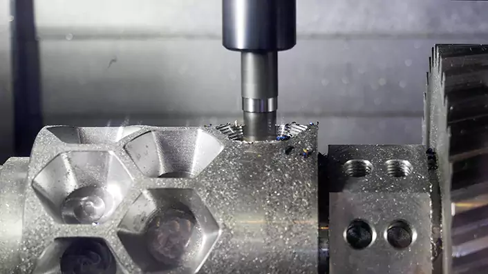
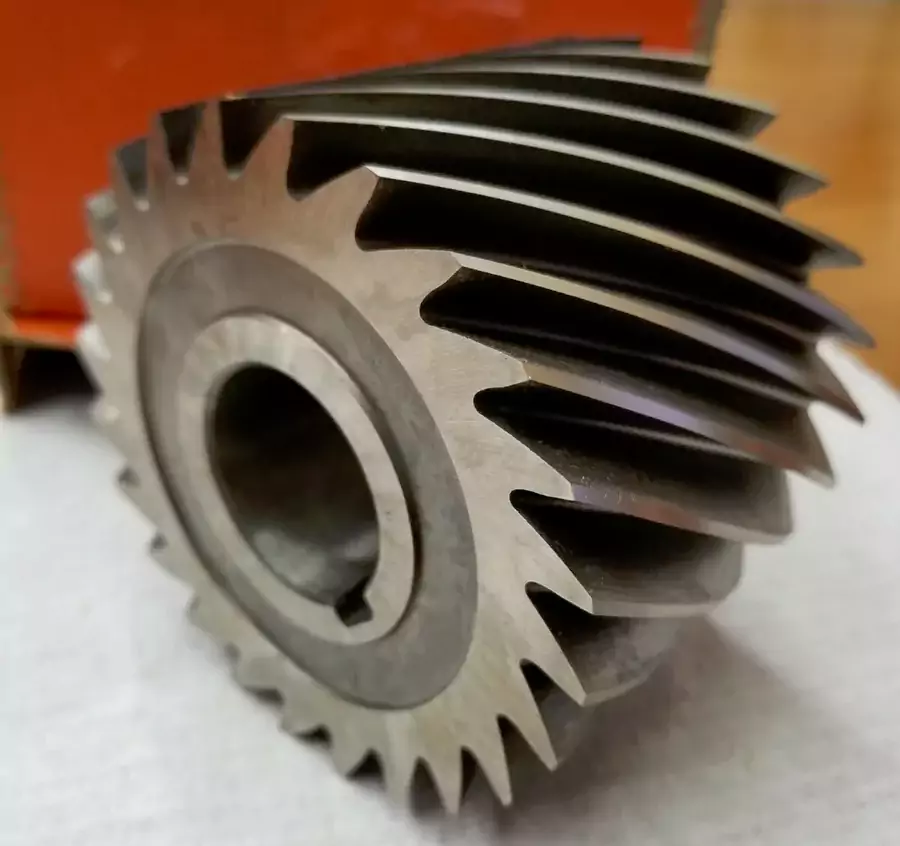
- Specific Features Requirement:Certain features of a part necessitate 4-axis or 5-axis CNC machining, especially when leveraging the simultaneous movement of these axes, such as in the case of helical surfaces and impeller contours as in the pictures before.
- Reduced Setup Time:Some parts can be CNC machined using 3-axis CNC machining through multiple setups, but 4 or 5-axis CNC machining can significantly reduce the number of setups and, consequently, setup time. Although the unit time cost of 4-axis and 5-axis CNC machining is higher, if the total machining time is substantially reduced, it becomes more cost-effective than 3-axis CNC machining.
- Strict Geometric Tolerance Requirements:For parts with stringent geometric tolerance requirements, like perpendicularity and concentricity, multiple setups on a 3-axis CNC machine may lead to tolerance deviations. In such cases, 4-axis or 5-axis CNC machining is necessary to ensure precise geometric tolerances by utilizing the rotation of the fourth and fifth axes instead of relying on multiple setups and fixture precision on a 3-axis CNC machine.
When not to use 4- or 5-axis milling?
Compared to 3-axis CNC machines, 4-axis and 5-axis milling machines are more expensive, with a higher unit cost per machining time. The advantage of 4-axis and 5-axis machines lies in their ability to reduce the number of setups and, consequently, setup time. In the case of large production batches, 3-axis CNC machining can offset the advantages of 4-axis and 5-axis CNC machining by employing custom quick fixtures, automated clamping methods, and other techniques to minimize setup time. Therefore, in high-volume production, where the time saved on setups is less critical, 3-axis CNC machining may be more suitable.
Conversely, for small production batches, where investing in custom fixtures might not be cost-effective, setup time constitutes a significant proportion of the overall machining time. In such scenarios, 4-axis CNC machining and 5-axis CNC machining become more favorable.
Another consideration for 4-axis and 5-axis CNC machines is their size constraints. The presence of the fourth and fifth axis occupies a portion of the machining space. Consequently, the size of parts (raw materials) that can be accommodated by 4- and 5-axis machines is significantly smaller compared to same-tier 3-axis CNC machines. Therefore, if the parts are excessively large, exceeding, for example, 1 meter, finding and affording a suitable 5-axis machine becomes challenging.
Axis Linkage, 3+1 axis CNC machining, 3+2 CNC machining, Five-Axis Simultaneous Machining
In CNC milling, when various axes of the machine can move simultaneously during processing, it is referred to as “linkage.” While all CNC milling machines can have simultaneous movement along the XYZ axes, not all 4- or 5-axis CNC machines can link the fourth or fifth axis simultaneously. A 4-axis machine that cannot link the fourth axis is termed the 3+1 axis or fake 4-axis, and a 5-axis machine unable to link the fourth and fifth axis is called a 3+2 axis or fake 5-axis.
During processing, a 3+1 CNC milling machine needs to rotate the fourth axis to a specific position and then fix it in place for part processing. Cutting cannot be done while the fourth axis is rotating. Some parts that can be processed on a true 4-axis machine cannot be processed on a fake 4-axis machine. For instance, the helix shown in the image below is one such example.
The situation is similar for a 5-axis CNC machine. A 3+2-axis CNC milling machine must process parts with the fourth and fifth axes fixed without rotation. It cannot handle complex surfaces like fan blades that require simultaneous movement of the fourth and fifth axes during processing.
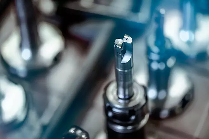
Tool
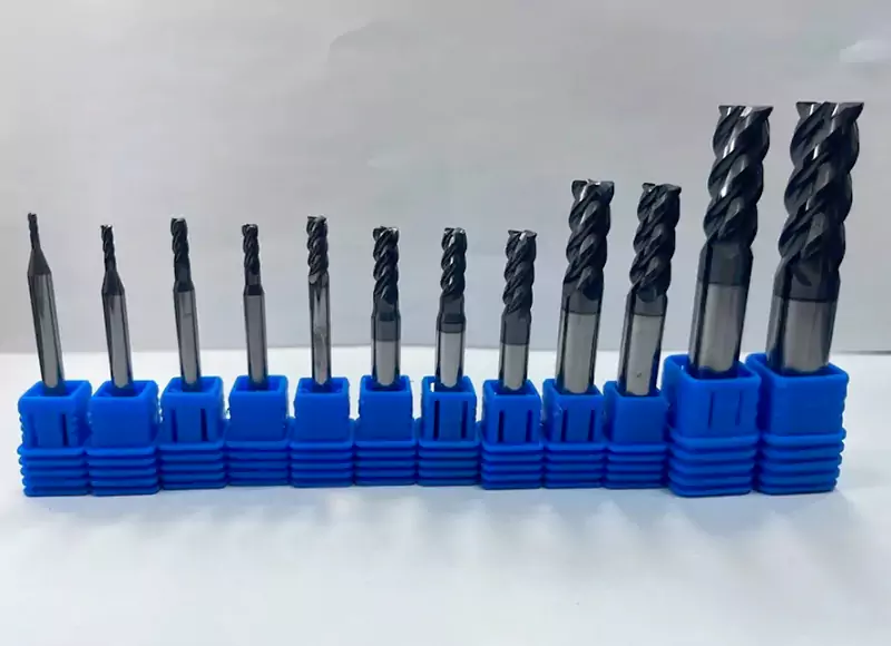
A milling cutter is a rotating cutting tool used in milling machines or machining centers to remove material from a workpiece. It consists of one or more cutting edges, usually made of high-speed steel (HSS) or carbide, that rotate and cut into the workpiece. Milling cutters can come in a variety of shapes and sizes, each designed for a specific purpose and application. It is an important tool in manufacturing blades and is widely used in CNC machining services.
What feature is the milling cutter?
Milling cutters are versatile tools used in machining processes to remove material from a workpiece. They come in various types and sizes, each designed for specific applications. Here are some key features of milling cutters:
Material Composition:
Milling cutters are typically made from high-speed steel (HSS), carbide, or sometimes ceramic materials.
Carbide cutters are popular for their hardness and durability, providing longer tool life and higher cutting speeds.
Cutting Edges:
Milling cutters have multiple cutting edges, which can range from one to more than a dozen, depending on the type of cutter. The cutting edges can be on the periphery, the end face, or both, allowing for various cutting actions.
Geometry:
The geometry of the cutter influences its cutting capabilities. Common geometries include square, ball nose, corner radius, and chamfer, each suited for specific tasks.
Different cutter geometries are chosen based on the desired surface finish, material type, and machining operation.
Shank Type:
The shank is the part of the milling cutter that is gripped by the machine spindle. Common shank types include straight shank and tapered shank (such as Morse taper or R8 taper).
Coating:
Some milling cutters may have coatings to enhance their performance. Common coatings include TiN (titanium nitride), TiCN (titanium carbonitride), and TiAlN (titanium aluminum nitride), which provide improved hardness and wear resistance.
Helix Angle:
For certain cutters like end mills, the helix angle (the angle between the cutting edge and the axis of rotation) affects chip evacuation, cutting forces, and surface finish.
Flutes:
Flutes are the grooves or channels on the milling cutter that help evacuate chips from the cutting area. The number of flutes can vary, and the choice depends on factors such as material type and machining conditions.
Application-Specific Features:
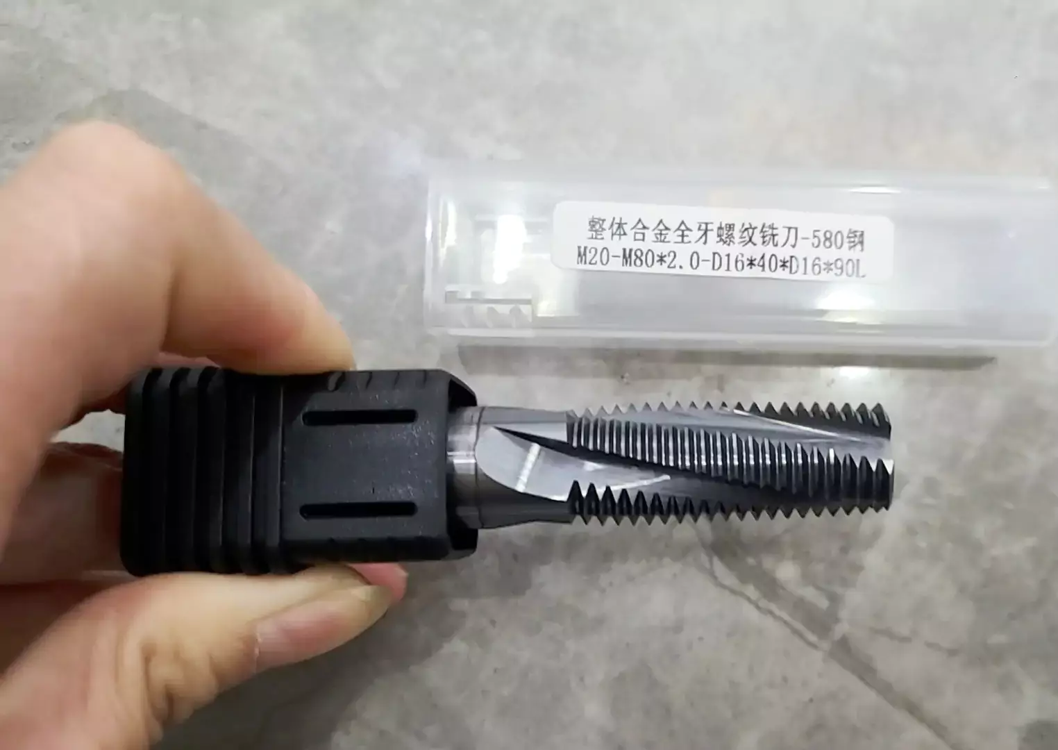
Some milling cutters are designed for specific applications, such as keyseat cutters for cutting keyways, T-slot cutters for milling T-shaped slots, and thread mills for machining threads.
Size and Diameter:
Milling cutters come in various sizes and diameters to accommodate different machining requirements. The size and diameter influence the depth of cut and the overall stability of the cutter.
Coolant Channels:
Some milling cutters may have built-in coolant channels to facilitate the efficient removal of heat generated during the machining process.
Understanding these features is crucial for selecting the right milling cutter for a specific machining task, ensuring optimal performance and tool longevity.
Common types of milling cutters include:
End Mill:
An end mill is a versatile milling cutter with cutting edges on both the end face and the sides, designed to remove material from a workpiece. Common types include square end mills for general applications, ball nose end mills for 3D profiling, corner radius end mills for rounded corners, and chamfer end mills for creating chamfered edges. The number of flutes, helix angle, and coatings vary, influencing chip evacuation, tool rigidity, and wear resistance.
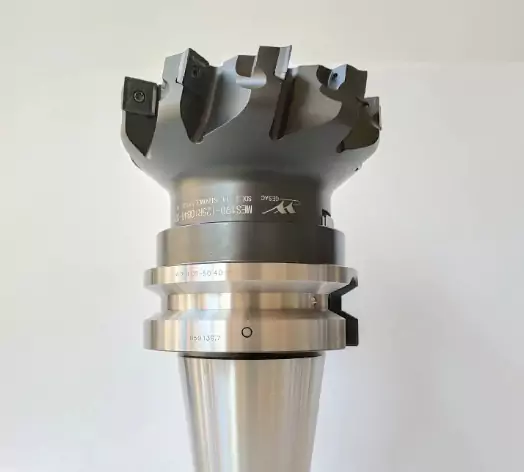
Face Mill:
A face mill is a milling cutter designed for removing material from the face of a workpiece. It features cutting edges on the face as well as the periphery, allowing efficient material removal in both axial and radial directions. Face mills are commonly used for facing large flat surfaces, producing smooth finishes. They come in various sizes and configurations, with multiple inserts or cutting edges. The tool’s geometry and coatings influence its performance in terms of speed, chip evacuation, and wear resistance. Face mills are essential in manufacturing processes for industries such as metalworking, where flat surface machining is prevalent.
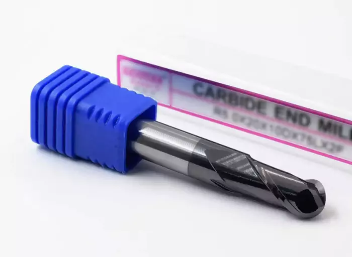
Ball Nose Cutter:
A ball nose cutter is a specialized milling tool with a rounded end designed for intricate 3D contouring and profiling. Featuring a spherical tip, it allows for smooth and precise carving of curved surfaces in materials like metal or wood. The unique design minimizes cutting forces and reduces the risk of workpiece damage. Ball nose cutters are commonly used in sculpting, engraving, and machining applications where detailed and contoured surfaces are essential. The size, radius, and number of flutes in the cutter impact its performance, making it a valuable tool in industries such as aerospace, automotive, and mold-making for intricate machining tasks.
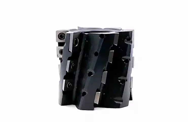
Shell Mill:
A shell mill is a milling cutter characterized by its large diameter and cutting edges on its periphery, primarily used for high-speed milling of large flat surfaces. It resembles a hollow shell, allowing for efficient material removal across expansive workpieces. Shell mills come in various sizes, accommodating diverse applications in industries like manufacturing and metalworking. The tool’s design provides stability and rigidity during operation, ensuring consistent and precise surface finishes. Commonly used with multiple inserts, shell mills are essential for facing operations and profiling large workpieces, making them indispensable in applications such as aerospace, automotive, and heavy machinery manufacturing.
Slab Mill:
A slab mill is a type of milling cutter designed for machining large, flat surfaces in a single pass. Characterized by its wide cutting edge, the slab mill efficiently removes material across expansive workpieces, enhancing productivity. This tool is commonly used in heavy-duty milling operations, such as face milling or surface milling of large components. The robust design and broad cutting surface contribute to the stability and precision required for handling significant material removal. Slab mills find application in various industries, including manufacturing, construction, and shipbuilding, where the efficient milling of extensive flat areas is essential for achieving precise and smooth finishes.
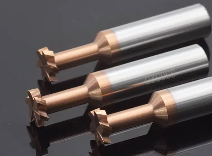
T-slot Cutter:
A T-slot cutter is a specialized milling tool designed to cut T-shaped slots or channels into workpieces, typically used in machine tables and fixtures. This cutter features a cutting head with a T-shaped profile, allowing for the creation of precise slots that accommodate T-shaped fasteners or workpiece positioning. T-slot cutters are essential in machine tool setups, enabling the secure fixation of components using T-bolts and nuts. These cutters come in various sizes to match different T-slot dimensions, offering versatility for a range of applications. Widely used in metalworking and machining, T-slot cutters contribute to the efficient and accurate construction of workholding systems.

Keyseat Cutter:
A keyseat cutter is a specialized milling tool designed for cutting keyways or slots in shafts, hubs, or other cylindrical objects. Featuring a straight or staggered-tooth design, this cutter creates precisely sized and shaped keyways, allowing for the secure fitting of keys and key stock. Keyseat cutters are vital in machinery and equipment assembly, providing a means to secure gears, pulleys, and other rotating components onto shafts. Available in various sizes and configurations, these cutters contribute to the precise and efficient machining of keyways, ensuring proper alignment and functionality in applications across industries such as manufacturing, automotive, and mechanical engineering.
Fly Cutter:
A fly cutter is a single-point cutting tool used in machining for facing and smoothing large flat surfaces. Consisting of a single cutting tool mounted on a spindle, it rotates and engages with the workpiece. Fly cutters are typically used at low speeds and produce a smooth finish across the surface. They are commonly employed for facing operations on milling machines and are advantageous for their simplicity and cost-effectiveness. Despite their single-point design, fly cutters are capable of achieving accurate finishes, making them suitable for various applications in metalworking and woodworking where precision flat surfaces are required.
Milling cutters are crucial in various CNC machining processes, allowing for precise and efficient material removal. The selection of the appropriate milling cutter depends on factors such as the type of material being machined, the desired surface finish, and the specific machining operation.
What is a tool holder?
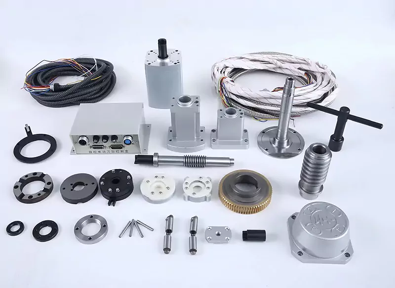
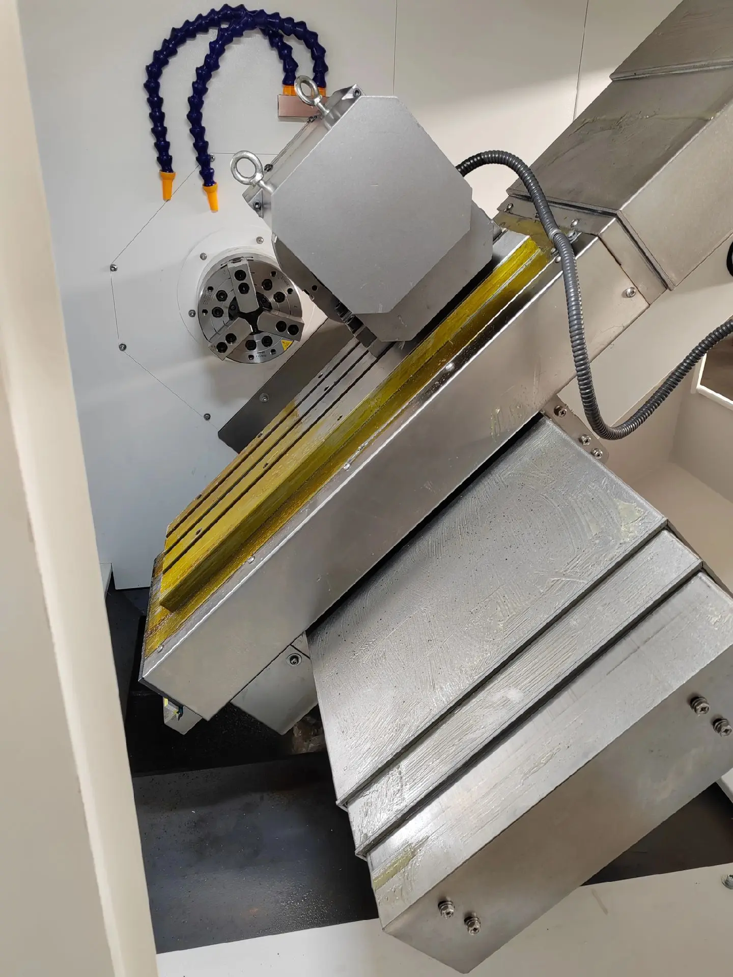
CNC machine tool is composed of a spindle, tool changer (tool holder and tool magazine manipulator), ball screw, and other functional components. Most of the machine tool companies through outsourcing and outsourcing of different functional components and combined assembly, build a complete machine tool.
Therefore, the reliability level of functional components will have a direct impact on the reliability level of the machine and CNC machining. Therefore, the key to improving the reliability level of CNC machine tools is to improve the reliability of key functional components of CNC machine tools.
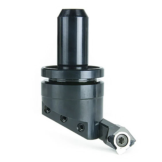
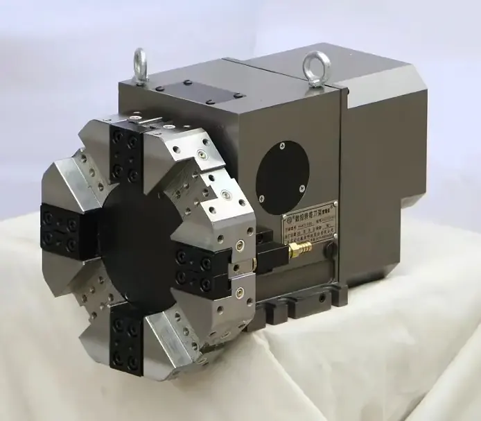
The tool holder of a CNC machine tool is the mechanical component that supports and fixes the tool, which plays a crucial role in CNC machining. The design and function of the tool holder directly affect the machining accuracy, efficiency, and stability of the CNC machine tool.
It is one of the key functional components of a CNC lathe, and its reliability directly affects the stability and reliability of the whole machine. By realizing process integration and tool change automation, the CNC tool holder significantly reduces the time of tool change, and it ensures the positional accuracy of the lathe tool.
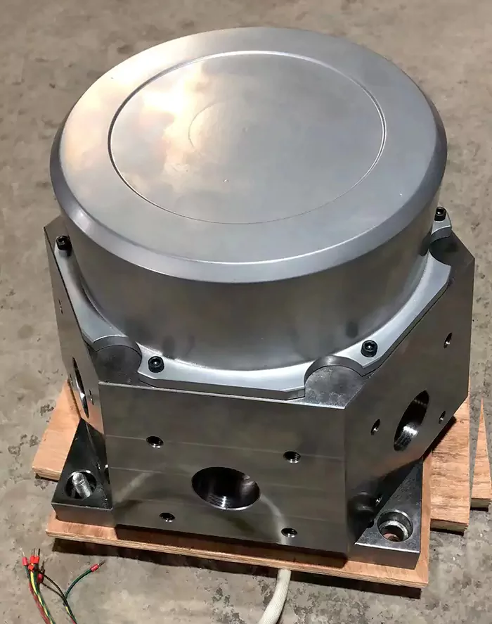
Components of a tool holder:
Main Structure: The main structure of the tool holder is usually made of cast iron or welded steel plate to ensure sufficient rigidity and stability. This part is subjected to cutting forces and various loads during the machining process.
Guideway System: The guideway system is responsible for supporting and guiding the movement of the tool and usually consists of linear guideways and components such as ball screws to ensure accurate and stable tool movement.
Tool clamping system: This part includes various components of the clamping tool, such as the chuck, clamping tool holder, etc., and its design directly affects the stability of the tool and the efficiency of tool change.
Tool Adjustment Device: The tool adjustment device allows small adjustments to be made to the tool to achieve accuracy and versatility in the machining process.
Cooling System: The cooling system is used to cool the tool to prevent overheating due to friction during the machining process and also helps to extend the tool’s life.
Holder Type:
CNC machine tool holders can be categorized into many types based on their application, structure, and characteristics. The following are some common types of CNC machine tool holders:
Horizontal Toolholders: Horizontal tool holders are horizontal tool holders with the tool perpendicular to the work plane. This type of holder is suitable for horizontal milling, drilling, and cutting operations.
Vertical Tool Holder: The vertical tool holder is a vertically oriented tool holder with the cutter horizontal to the work plane. It is typically used for vertical milling, drilling, and cutting operations.
Gantry Tool Holder: A gantry tool holder is a large tool holder structure in which the tool holder moves along a gantry structure that spans the entire machining area. This type of holder is commonly used for machining large workpieces such as steel structures, ships, and airplane parts.
Arm Type Tool Holder: An arm-type tool holder is a crossbeam type of tool holder with a tool holder that moves along an arm structure. This type of holder is often used to achieve complex workpieces such as automobile engine blocks and automobile frames.
Bridge-type tool holders: Bridge-type tool holders are similar to gantry-type tool holders, but are simpler in construction, with the tool holder spanning the work plane. This type of tool holder is usually used for higher precision requirements of processing, such as mold processing and precision parts processing.
Rotary tool holder: The rotary tool holder has the function of tool rotation, which can realize the machining of complex contours, such as curved surfaces and three-dimensional parts.
Compound tool holders: Compound tool holders combine the functions of multiple tool holders to realize a variety of machining operations, such as milling, drilling, tapping, and cutting.
Importance of the tool holder
Machining accuracy: The design and structure of the tool holder directly affect the machining accuracy of the CNC machine tool. A stable and solid tool holder can effectively minimize vibration and deformation, thus ensuring that the dimensions and surface accuracy of the machined parts meet the requirements.
Machining Efficiency: A well-designed tool holder can improve the machining efficiency of a CNC machine tool. It can support various cutting operations and ensure fast and accurate tool movement, thus reducing machining time and cost.
Stability: The stability of the tool holder is directly related to the stability of the CNC machine tool. A solid tool holder can effectively reduce vibration and oscillation during the machining process, ensuring the stability and reliability of the machining process.
Tool life: Proper tool holder design reduces tool wear and damage, thereby extending tool life and reducing replacement and maintenance costs.
Versatility: The design of the tool holder should also take into account the versatility of different machining requirements. It should be able to accommodate various types and sizes of tools and support different types of machining operations, thus increasing the application range and flexibility of the CNC machine tool.
History and Development
Since the middle of the 20th century, computer technology has developed rapidly, and digital control technology has been widely used in the manufacturing industry. The introduction of computers provides technical support for automation and precision control, and to work in concert with CNC technology to adapt to the new machining environment, CNC tool holders have emerged.
The generation of the CNC tool holder replaces the traditional manual tool holder and realizes the automatic tool change function of the lathe in the process of machining the workpiece.
The CNC tool holder as a key functional component of the CNC lathe, mainly bears the role of cutting tool clamping and replacement. The rigidity and indexing accuracy of the CNC tool holder plays a decisive role in determining the position of the tooltip, which directly affects the machining accuracy of the workpiece to be machined.
So far, the electric tool holder and hydraulic tool holder have occupied the main market of tool holders, and become the mainstream tool holder products, driven by electric motors electric tool holders are prevalent in Europe, while Japan and South Korea mainly promote hydraulic motor-driven CNC tool holder.
Since the 1950s, the United States K & T successfully developed the first automatic tool changer, and researchers in various countries began to focus on its reliability.
More representative tool holder companies mainly include Germany DMG MORI, the United States Haas Automation, Japan Mazak, and so on.
German DMG MORI CNC tool holders are famous for their high precision and high performance, and they are usually equipped with advanced tool management systems, which can monitor, manage, and optimize the status of the tool, thus improving the efficiency of the machine tool.
Haas Automation is an excellent manufacturer of CNC machine tools and cutting tools, specializing in the design and production of high-performance CNC machine tools and related accessories, known for its high-performance CNC tool holders. Haas Automation’s CNC tool holders usually include automatic turret systems, which can achieve rapid and automatic tool change and improve productivity.
Japan’s Mazak is also an excellent manufacturer of CNC machine tools. Its product line includes a variety of high-precision CNC tool holders, and its CNC tool holders are usually equipped with a multi-axis turret system, which realizes the automatic switching of multiple tools and improves cutting efficiency.
The main manufacturers of CNC tool holders in Taiwan, China include Luk Hsin Co., Ltd, Taiwan Sunrise International Precision Machinery Co., Ltd, and Taiwan Tex Co.
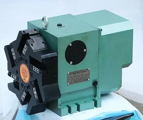
Conclusion
Facing the development wave of intelligence and integration, CNC machine tools have become the core carrier of manufacturing development. As an important part of the CNC machine, improving the reliability of CNC tool holders is a must for the development of high-quality products.
With the continuous breakthrough of scholars in reliability technology, the theory and engineering practice related to the reliability of CNC tool holders will be further developed.
Materials
Speaking of materials, there are many types, and we must understand their characteristics. It will be of great help to our processing.
Metal
Some metals are more challenging to CNC machine than others due to factors such as hardness, toughness, thermal conductivity, and chip formation characteristics. Conversely, certain metals are easier to CNC machine because they exhibit favorable machining properties. Here’s a breakdown:
Difficult to CNC Machine:
- Titanium: Titanium alloys are known for their high strength, toughness, and low thermal conductivity, making them challenging to machine. Titanium tends to work harden and generate high cutting temperatures, leading to tool wear, surface defects, and poor chip evacuation.
- Stainless Steel: Stainless steels, especially those with higher alloy content such as 300 series (e.g., 316, 304) or duplex stainless steels, are difficult to machine due to their work-hardening tendency, abrasive nature, and high cutting forces. Proper tool selection, coolant usage, and cutting parameters are essential for effective machining of stainless steel.
- High-temperature Alloys: Metals such as Inconel, Hastelloy, and Monel are challenging to machine due to their high strength, heat resistance, and tendency to work harden at elevated temperatures. These alloys are commonly used in aerospace, automotive, and chemical processing industries, requiring specialized cutting tools and machining techniques.
- Tool Steels: Hardened tool steels, used for making cutting tools and molds, are difficult to machine due to their high hardness and abrasiveness. Machining tool steels typically requires carbide or ceramic cutting tools and slow cutting speeds to minimize tool wear and maintain dimensional accuracy.
Easy to CNC Machine:
- Aluminum: Aluminum and its alloys, such as 6061 and 7075, are widely used in CNC machining due to their low density, excellent machinability, and good thermal conductivity. Aluminum chips form easily, and the material dissipates heat effectively, resulting in improved chip evacuation and reduced tool wear.
- Brass: Brass is another metal that is relatively easy to CNC machine due to its softness, low friction coefficient, and excellent chip formation characteristics. Brass alloys, such as C360 (free-cutting brass), are commonly used in precision machining applications, including fittings, valves, and electrical components.
- Copper: Like brass, copper is soft and ductile, making it easy to machine. Copper alloys, such as C110 (pure copper) and C360 (free-cutting brass), are commonly used in CNC machining for electrical connectors, heat exchangers, and plumbing components.
- Mild Steel: Low-carbon or mild steels are relatively easy to machine compared to high-strength or hardened steels. Mild steel offers good machinability, moderate hardness, and low cutting forces, making it suitable for a wide range of CNC machining applications.
While these classifications provide general guidelines, it’s essential to consider specific alloy compositions, machining conditions, and part geometries when determining the machinability of metals. Additionally, advancements in cutting tool technology, coolant systems, and CNC machine capabilities continue to expand the range of materials that can be effectively machined.
It’s essential to consider the specific requirements, properties, and cost implications when selecting metals for a particular application. Factors such as material availability, processing complexity, and lifecycle costs should also be taken into account to ensure optimal performance and cost-effectiveness.
Plastic
Some plastics are more challenging to CNC machine than others due to factors such as thermal properties, hardness, and machinability. Conversely, certain plastics are easier to CNC machine because they exhibit favorable machining characteristics. Here’s a breakdown:
Difficult to CNC Machine:
- Polycarbonate (PC): Polycarbonate is a tough and durable plastic known for its high impact resistance and clarity. However, it can be challenging to machine due to its tendency to melt and deform at high temperatures, resulting in poor surface finish and dimensional inaccuracies.
- Polyether Ether Ketone (PEEK): PEEK is a high-performance engineering plastic with excellent mechanical properties, chemical resistance, and temperature resistance. However, its high melting point and abrasiveness make it difficult to machine, requiring specialized cutting tools and coolant strategies to achieve satisfactory results.
- Polytetrafluoroethylene (PTFE): PTFE, commonly known as Teflon, is a low-friction plastic with excellent chemical resistance and non-stick properties. However, its soft and slippery nature makes it challenging to machine, as it tends to deform and create built-up edge on cutting tools.
- Acrylic (PMMA): Acrylic is a transparent thermoplastic known for its optical clarity, impact resistance, and weatherability. While acrylic is relatively easy to cut and shape, it can be prone to chipping, melting, or cracking if not machined with proper tooling and techniques.
Easy to CNC Machine:
- Acetal (Polyoxymethylene, POM): Acetal is a versatile engineering plastic known for its high stiffness, low friction, and excellent dimensional stability. It is relatively easy to machine, offering good chip control, low tool wear, and smooth surface finish.
- Polyethylene (PE): Polyethylene is a widely used plastic known for its low cost, chemical resistance, and ease of processing. It is relatively easy to CNC machine, with good machinability and low tool wear, making it suitable for a variety of applications.
- Polypropylene (PP): Polypropylene is a lightweight and versatile plastic known for its high chemical resistance, low moisture absorption, and good impact strength. It is easy to CNC machine, with good machinability and low melting point, resulting in smooth surface finish and minimal tool wear.
- Nylon (Polyamide, PA): Nylon is a tough and abrasion-resistant plastic known for its high strength, stiffness, and wear resistance. It is relatively easy to machine, offering good chip control, low friction, and dimensional stability, especially in reinforced grades such as nylon 6/6.
>> Metal material for CNC Machining
>> Plastic material for CNC Machining
Human Resouce
When all the physical conditions of the party, such as machines, cutting tools, fixtures, and materials, can meet our ideal working conditions, we cannot ignore the human factor. In the final analysis, all these material things are prepared for us humans to some extent. In a perfect CNC machining process, who will be involved?
- Design Engineers: Design engineers are involved in the initial stages of the process, responsible for creating CAD (Computer-Aided Design) models of the parts to be machined. They design parts with consideration for manufacturability, tolerances, and functional requirements.
- Manufacturing Engineers: Manufacturing engineers are responsible for planning and optimizing the CNC machining process. They select appropriate machining techniques, tooling, cutting parameters, and workholding methods to achieve the desired outcomes efficiently and cost-effectively.
- CNC Programmers: CNC programmers translate CAD models into machine-readable G-code instructions that drive the CNC machine’s movements. They develop CNC programs using CAM (Computer-Aided Manufacturing) software, specifying toolpaths, cutting parameters, and tool changes.
- CNC Machine Operators: CNC machine operators are responsible for setting up, operating, and monitoring CNC machines during the machining process. They load cutting tools and workpieces, input CNC programs, and ensure that machines operate correctly and produce parts according to specifications.
- Quality Control Inspectors: Quality control inspectors perform inspections and measurements of machined parts using precision measuring instruments. They verify part dimensions, tolerances, and surface finish, ensuring that parts meet quality standards and customer requirements.
- Maintenance Technicians: Maintenance technicians are responsible for maintaining CNC machines in optimal condition. They perform routine maintenance tasks such as cleaning, lubrication, and minor repairs to prevent breakdowns and ensure machine reliability.
- Supervisors and Managers: Supervisors and managers oversee the CNC machining process, coordinating activities, managing resources, and ensuring that production targets are met. They provide guidance, support, and resources to ensure the smooth operation of the process.
- Health and Safety Personnel: Health and safety personnel ensure that the CNC machining process complies with regulatory standards and industry best practices for workplace safety. They identify and mitigate safety hazards, provide training to operators, and enforce safety protocols.
So when an operator stands in front of the machine and enjoys the happiness of an engineering man, there is a team behind him to support him. Without a team, it is not easy to do CNC processing well.
Of course, everyone needs professional corresponding knowledge. There are many excellent universities in various industrialized countries cultivating such talents.
Environmental
Today, CNC machining can achieve an accuracy of ±0.0002 inches (0.005 mm) and beyond. Therefore, an issue that cannot be ignored is the impact of the environment on CNC processing. We have to consider his existence.
Environmental factors can significantly impact CNC machining precision. Some of the key environmental factors include:
Temperature: Temperature variations in the machining environment can cause thermal expansion or contraction of machine components, affecting dimensional accuracy and stability. Fluctuations in temperature can also lead to changes in material properties, tool performance, and chip formation.
Humidity: High humidity levels can cause moisture absorption in machine components, affecting their dimensional stability and leading to changes in machining accuracy. Additionally, humidity can contribute to corrosion, rusting, and degradation of machine surfaces and cutting tools.
Vibration: Vibrations from external sources such as nearby machinery, floor vibrations, or improper machine installation can negatively impact machining precision. Vibrations can cause tool chatter, poor surface finish, and dimensional inaccuracies in machined parts.
Dust and Contaminants: Dust, debris, and airborne contaminants in the machining environment can accumulate on machine surfaces, ball screws, linear guides, and other critical components. Contaminants can interfere with machine motion, increase friction, and lead to accelerated wear and tear, affecting machining precision and reliability.
Noise: Excessive noise levels in the machining environment can indicate mechanical issues such as worn bearings, misalignment, or improper machine operation. Noise can also affect operator concentration and fatigue, leading to errors in machining setup or operation.
Lighting: Inadequate or uneven lighting in the machining area can make it difficult for operators to visually inspect machined parts, tooling, and machine conditions accurately. Proper lighting is essential for maintaining quality control and ensuring accurate machining operations.
Air Quality: Poor air quality due to dust, fumes, or chemical vapors can pose health risks to machine operators and affect machine performance. Adequate ventilation and filtration systems are necessary to maintain a safe and healthy working environment for operators and to prevent contamination of machine components.
Electromagnetic Interference (EMI): Electromagnetic interference from nearby electronic devices or electrical equipment can disrupt signals in CNC machine control systems, leading to communication errors, signal noise, and erratic machine behavior. Proper shielding and grounding measures are necessary to minimize EMI effects on CNC machining precision.
By addressing these environmental factors and implementing appropriate mitigation measures, manufacturers can maintain CNC machining precision and ensure consistent quality in machined parts. Regular maintenance, monitoring, and calibration of CNC machines and environmental control systems are essential for optimizing machining performance and minimizing the impact of environmental variables.
References:
- [1] A. Keller, A. Kamath, U. Perera Reliability analysis of CNC machine tools Reliab. Eng., 3 (1982), pp. 449-473