How is CNC machining programmed?
CNC lathe is one of the widely used CNC machine tools. Similar to ordinary lathes, CNC lathes are mainly used to process rotary body parts such as shafts and disks. In ordinary turning, the quality and efficiency of the parts depend largely on the experience of the operator. CNC turning machining, on the other hand, is carried out through pre-programmed programs. This is because CNC machining programs include not only the machining process of the part but also key process information such as the determination of the tool cutting dosage and the route of tool travel.
The use of CNC lathes in various countries nowadays has greatly provided the quality and efficiency of machining as it utilizes many advanced technologies. The use of traditional ordinary lathes has also been greatly reduced in favor of less economically developed areas or technology enthusiasts.
This paper takes a shaft part as an example, its CNC machining process is analyzed and programmed in detail.
Parts drawing analysis
Figure 1 is the part drawing of the shaft parts. It is known that the blank of the part is Φ30mm aluminum alloy, and it is required to machine M10×1 external thread, 3mm wide withdrawal groove, Φ15mm cylindrical surface, r7.5 concave circular surface, Φ20mm total length 11mm conical surface at the big end, R12.5 convex circular surface, and Φ24mm cylindrical surface on the CNC lathe of FANUC0i system. The dimensional tolerances of the cylindrical surface of Φ24mm are upper tolerance +0.021mm, lower tolerance 0. The surface roughness of the cylindrical surface of Φ24mm and Φ15mm of this workpiece is Ra3.2μm, the surface roughness of the circular surface of Ra12.5 is Ra6.3μm, and the surface roughness of the other surfaces is Ra12.5μm, and the roughness of the other surfaces is rA12.5μM, which needs to be arranged for roughing and finishing machining in the machining.
Determine the machining process
1. Workpiece clamping and positioning
The parts clamping selection of general-purpose three-jaw self-centering chuck clamping parts of the blank outer circle, the workpiece should be clamped in the clamping force should be moderate, the clamping force is too easy to clamp the workpiece, clamping force is not enough to cause the workpiece loosening in the process of machining, the parts out of the length of the machine tool should be taken into account to limit distance (machine tool equipped with a limit of the bumper block), the parts of the processing of the total length of 70mm, so the parts out of the end of the chuck from the end of the surface of the chuck is about 90mm.
2. Determination of machining tools
Analyze the parts diagram, to determine the processing of the parts need to use a 90 ° cylindrical turning tool, sharp cylindrical turning tool (turning surface with), thread turning tool, and cut off the knife.
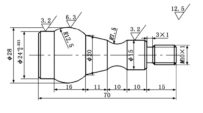
Fig 1
3. Determination of cutting dosage
The cutting amount of CNC turning includes the amount of depth of cut, spindle speed, and feed rate. Before programming, should reasonably select the amount of feed, back eating amount, and spindle speed, only these three are adapted to each other, in order to form the best machining results, the following outside the circular turning tool cutting the amount of selection and calculation as an example to analyze.
(1) Determination of the amount of depth of cut. Combined with the rigidity of the machine tool system and the quality of the tool used, the roughing of each tool depth of cut amount of 3mm. due to the high machining accuracy requirements of the parts, so in addition to roughing, but also semi-finishing and finishing, semi-finishing back eating amount of 1mm ~ 1.5MM, finishing depth of cut amount of 0.5mm.
(2) Determination of spindle speed N. The spindle speed N should be determined according to the diameter of the part being machined as well as the material of the part, the material of the tool, and the cutting speed. In production, the spindle speed n (r/min) can be calculated according to the following formula:
n=1000vC/(πd)
Where: Vc for the cutting speed, after checking Table 1 and combined with its own tool quality to take Vc = 60m/min; d for the diameter of the workpiece, take the diameter of the workpiece d = 30mm. respectively, the cutting speed, the diameter of the workpiece is substituted into the formula (1), to find n ≈ 637 r/min, take the spindle speed n = 630 r/min.

Table 1 Cutting parameters of the tool
(3) Determination of feed rate. The size of the feed directly affects the surface roughness of the parts and machining efficiency, in order to ensure the surface quality of the parts under the premise of combining the tool, and parts materials, consult the cutting manual to select the feed amount of 0.3 mm/r.
4. Position point
In the programming should choose the appropriate workpiece zero point and tool change point.
(1) Workpiece zero point. In order to meet the conditions of programming simplicity and less dimensional conversion, caused by small machining errors, the workpiece coordinate origin and program origin of the part should be placed in the center of the right end face of the workpiece.
(2) Tool change point. In order to prevent the tool from colliding with the workpiece or tailstock during tool change and to save time for moving the tool change, the tool change point should be set at the position of (X100, Z100).
5. Design of the turning method
(1) Use G94 (end face cutting cycle instruction) for flat end face.
(2) Roughly turn each part of the part contour as shown on the roadmap with G71 according to Fig. 2. (G71 inner and outer diameter roughing compound cycle instruction)
(3) Use G01, G02, and G03 in combination for continuous finish turning of the part contour.
(4) Machining M10×1 threads with G92 (thread cutting cycle instruction).
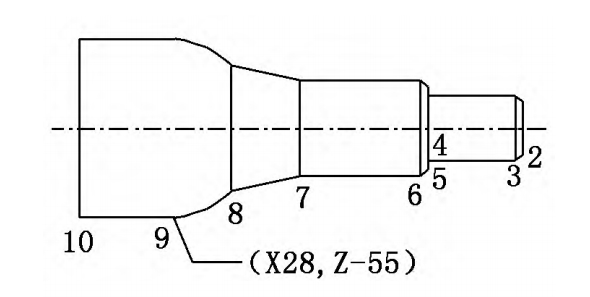
Fig 2
Programming
First, call the No.1 external turning tool to rough turn the parts, secondly, call No.2 pointed external finishing tool to finish turning the parts until the part size, then call the No.3 external thread turning tool to process the M10×1 thread, and finally use No.4 cut-off tool to turn off the workpiece.
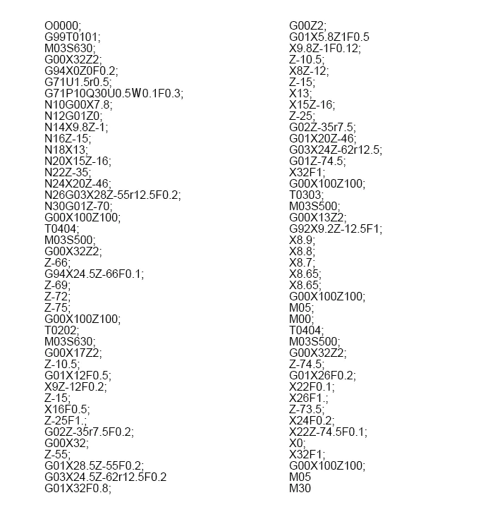
The reference program for shaft parts machining is as follows:
Conclusion
The development of the machining process is the preliminary preparation work of CNC turning, whether the process is developed reasonably, the quality of parts processing and machine tool machining efficiency have a great impact.
Therefore, abiding by the principle of process, combined with the processing characteristics of CNC lathe, developing a good CNC turning machining process of parts is the guarantee of processing qualified parts.