A thread rolling method based on CNC lathes
After using CNC horizontal turning equipment to process long shaft type threads (such as hydraulic press tie rods), due to the problem that the turning tool can not meet the machining requirements of the bottom of the threads or machining accuracy, there is a right angle or roughness at the bottom of the threads, resulting in stress concentration in the stress is easy to break, the need to roll on the bottom of the threads, the surface metal being rolled will produce plastic deformation.
After rolling on the bottom of the thread, the bottom of the thread is rounded, reducing the roughness, reducing the stress on the bottom of the thread, improving the force on the threaded section, and improving the hardness and strength of the part.
At present, when the bottom of the thread rolling processing, most of the ordinary lathe manual operation rolling, this way is simpler, easy to adjust in the processing, but the manual operation is easy to misoperation to produce damage, more dependent on manual experience, production quality is difficult to be consistent.
Although the CNC lathe for automated processing, as long as the start of processing can be processed in accordance with the preset processing program, reducing manual operation, production quality is more uniform.
However, because when the CNC lathe after the implementation of the processing program, can not stop in the middle, need to finish processing to stop, and rolling processing is different from cutting processing, so for the thread rolling processing requirements are relatively high, if the rolling method is not correct, then the damage to the parts and tools, and even damage to the CNC lathe, there is a greater risk.
Therefore, at present, the industry rarely uses CNC lathe for thread rolling, the technicians in this field hope that there is a thread rolling method based on CNC lathe, which can realize automatic rolling processing and reduce the processing risk.
Realization program
In order to illustrate the realization process of the whole thread rolling program more clearly, the following figures are used to make a simple introduction.
Concrete realization
Before machining on a CNC machine, the hob 2 and the threaded section 11 of the workpiece 1 to be rolled are aligned, so that the hob 2 can move precisely in the screw groove 111 during the machining process.
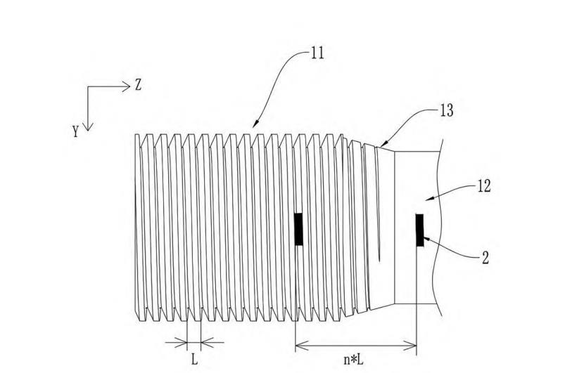
To do this, the hob 2 is first moved to the side of the threaded section 11 and set to the Z-axis coordinates of the starting point of the tool during machining;
The hob 2 is then moved along the Z-axis in integral multiples of the pitch, without moving the hob 2 along the Z-axis during the tool setting process;
Then, manually rotate the workpiece 1 and move the hob 2 along the X-axis so that the screw groove 111 can face the hob 2, and the hob 2 enters into the screw groove 111 and contacts the bottom of the tooth. At this time, set the X-axis coordinates of the starting point of the tool, and set the current angle of the main spindle as the starting angle of machining, which means that it changes the starting angle of the main spindle for machining the workpiece originally.
Tool setting method: By moving the hob 2 from the starting point of the tool to the position of a multiple of the pitch and then no longer moving it along the Z-axis, manually rotating the workpiece 1 and the screw slot 111 to adapt to the position of the hob 2, the screw slot 111 moves a shorter distance on the Z-axis when the workpiece 1 is rotated for easy control and adjustment, and rotating the workpiece 1 is more accurate and convenient than moving the hob 2 on the Z-axis to minimize the damage caused to the threads by the excessive movement of the hob 2 along the Z-axis when it is in the screw slot 111. This reduces thread damage caused by excessive movement of the hob 2 along the Z-axis while it is in the slot 111.
Since the travel distance of the hob 2 from the starting point of the tool is an integer multiple of the pitch of the thread, the hob 2 will be able to enter the slot 111 during machining when the slot 111 is properly aligned in this position, and the position of the starting point of the tool is less demanding, and there is no need to align the tool with the end of the threaded section 11, thus realizing the convenience of aligning the hob 2 and the thread on a numerically-controlled machine and increasing the accuracy of tool alignment, and executing the machining program after the tool alignment is realized precisely. When accurate tool setting is achieved, the machining program is executed to start hobbing, and the hob 2 can smoothly hob the bottom of the teeth along the threads, realizing hobbing of the threads on the CNC machine tool and reducing the machining risk.
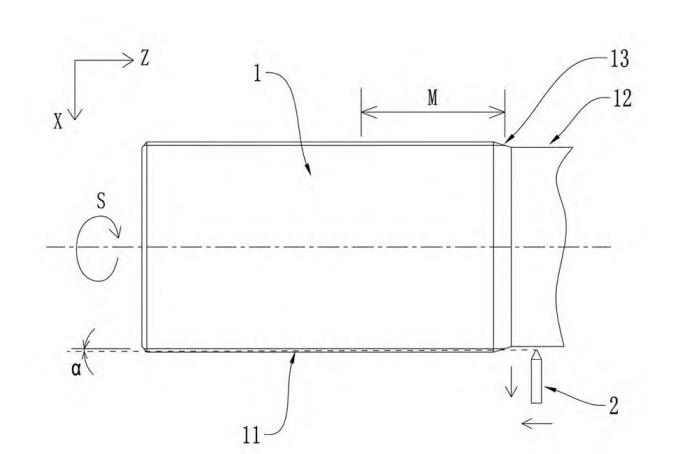
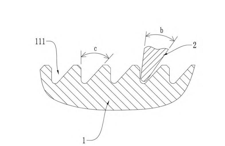
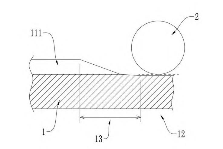
In some specific embodiments, the starting point of the tool is located in the backing groove 12 of the threaded section 11, the diameter of the backing groove 12 is smaller than the diameter of the bottom of the teeth of the threads, there is a transition ramp 13 between the threaded section 11 and the backing groove 12, and the end of the threads is on the transition ramp 13, which creates a beveled transition from the transition ramp 13 to the bottom of the teeth of the end of the threads, and the tops of the threaded portions of the threaded section on the transition ramp 13 will incline as the transition ramp 13 inclines to the bottom of the teeth of the threaded section. Furthermore, the top of the threaded portion of the transition bevel 13 is inclined with the transition bevel 13, i.e., the depth from the top of the thread to the bottom of the thread in the transition bevel 13 becomes progressively shallower, and the cross sectional size of the slot 111 becomes progressively smaller in the direction of the rebate groove 12, cf. FIGS. 3 and 5.
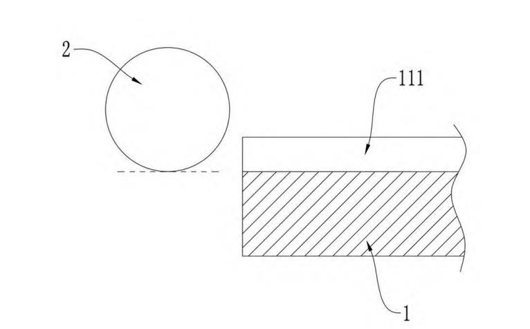
When the hob 2 approaches the threaded section 11 from the side of the retracting groove 12, the hob 2 first passes through the transition bevel 13 and gradually approaches the bottom of the teeth of the screw groove 111, gradually increasing the contact and pressure with the bottom of the teeth, and the cross-sectional size of the screw groove 111 gradually becomes bigger, and when the hob 2 just enters the screw groove 111, the heights of the screw teeth on both sides of the screw groove 111 are very small, and the hob 2 easily enters into the screw groove 111, referring to Fig. 5, which shows the depth from the top to the bottom of the teeth of the screw groove 111 along the direction of extension. Fig. 5 shows the cross-section of the screw groove 111 in the extension direction near the backing groove 12.
If the hobbing starts from the starting side of the cutting process of the threaded section 11, and this side is the end face, referring to FIG. 4, FIG. 4 shows the cross-section of the side of the screw groove 111 along the extension direction near the end face, the height of the bottom of the tooth may be high, the hob 2 may collide with the bottom of the tooth directly, and the pressure is high when it first comes into contact, and furthermore, there is no chamfer at the end of the threaded section 11 on this side or the chamfer is very small, the heights of the teeth of the screw groove 111 are high, and the hob 2 needs to enter into the threaded section 11 easily, referring to FIG. 5. In addition, the end of threaded section 11 on that side has no chamfer or the chamfer is very small, and the threads on both sides of slot 111 are relatively high, and the hob 2 needs to enter directly between the threads on both sides, and the position of the hob 2 and the slot 111 needs to be very precise in order to enter, or else it will be easy to hit the knife and damage the thread and the equipment.
This solution reduces or avoids direct collision of the hob 2 with the bottom of the tooth or the thread when it first enters the threaded section 111, resulting in smoother machining and further reducing the risk of thread rolling on a CNC lathe.
In some specific embodiments, the hob 2 moves along the Z-axis while moving at an angle along the X-axis away from the threaded segment 11. During the process of the hob 2, the bearings connected to the hob 2, as well as the bearings of the spindle are subjected to greater pressure and heat, which may burn out the bearings after a long period of time, or the spindle may be subjected to excessive force and shut down with an overload alarm, which affects the processing or even causes the equipment to malfunction.
Therefore, the hob 2 is set to move away from the threaded section 11 along the X-axis during the machining process, i.e., the hob 2 is tilted outward during the movement of the Z-axis, forming an angle α as shown in Fig. 1, and the depth of hobbing is gradually reduced and finally moved away from the bottom of the tooth, so that the hob 2 hobbing of the threaded section 11 is a section close to the retracting groove 12 instead of the whole threaded section 11, and the length of hob 2 is the length of actual hobbing in reference to the length M in Fig. 1, so that the machining time can be shortened. Moreover, the rolling pressure in the process is also reduced on the whole, and since the nut is mainly connected to the side of threaded section 11 near the recess 12 when the threaded section 11 of workpiece 1 is subjected to force in conjunction with the nut, i.e., the main stress position of threaded section 11 is in a section close to the recess 12, therefore, only rolling a section close to the recess 12 does not affect the normal use of workpiece 1, which reduces the pressure bearing time and pressure on the hob 2 and the main shaft, and further reduces the pressure on the CNC machine, and reduces the pressure on the CNC tool. This reduces the time and pressure of the hob 2 and the spindle, and further reduces the risk of thread rolling on the CNC lathe.
In some specific embodiments, the hob 2 can be rolled to the desired depth several times, reducing the pressure of each roll and reducing the load on the CNC lathe.
The multiple feed machining can be as follows: when rolling the first to the fourth cut, increase by 0.1 mm each time, gradually making the hob deeper to the desired depth;
When hobbing more than the fifth cut, such as the fifth cut to the tenth cut, the depth of the hob is not increased, the hob goes empty according to the depth of the fourth cut, and the bottom of the teeth of the entire thread is trimmed at that depth.
In some specific embodiments, the hob 2 includes a hobbing seat and a hobbing wheel rotationally connected to the hobbing seat, the hobbing wheel and the hobbing seat having an oscillating gap between the hobbing wheel and the hobbing seat for the hobbing wheel to adapt to the screw groove 111 during the hobbing process to oscillate to minimize damage to the screw threads due to machining errors.
Because of the oscillation clearance between the roller and the roller seat, the fit accuracy of the roller entering the screw groove 111 after the CNC lathe starts machining is required to be higher, and by using this method of tool setting, and by reducing the positional accuracy requirement of entering from one side of the retracting groove 12 as the starting point, the hob 2 can enter into the screw groove 111 more accurately.
Conclusion
The application of CNC lathe has become more and more popular, ordinary machine tools will slowly withdraw from the stage of history, this paper describes a CNC lathe-based thread rolling method, to solve the reality of the application of the application of no suitable ordinary lathe and the need to use the application of thread rolling occasions;
Solve the problem that the manual operation of ordinary machine tools in existing applications is easy to misoperate and the quality of production is difficult to be consistent;
Solve the technical problem of higher risk of using CNC lathe processing in existing applications, and finally provide a more efficient and quality-assured thread rolling processing solutions to promote the progress of machining process.