How to control the quality of sheet metal bending?
Sheet metal processing is widely used in various fields, such as aerospace, automotive electronics, railroad locomotives, and engineering machinery. Sheet metal bending is a key process in forming most parts, and the quality of bending directly affects the final shape and performance of the product.
Various factors affect the accuracy of sheet metal bending, such as the accuracy of the parts’ unfolding dimensions, the selection of molds, and the reasonableness of the bending sequence.
Therefore, the study of sheet metal bending accuracy must analyze these factors individually to determine how to control the bending quality and achieve a comprehensive improvement in bending quality.
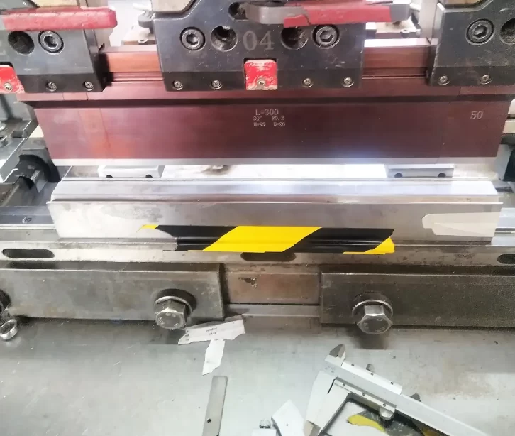
Calculation of sheet metal unfolding dimensions
(1) fittings bending radius design material bending, its rounded area of the outer layer is stretched, and the inner layer is compressed. When the material thickness is certain, the smaller the inner corner of the bending, the greater the ratio of tension and compression of the material; when the tensile stress of the outer corner of the rounded layer exceeds the ultimate strength of the material, it will produce cracks or fractures.
Therefore, the structural design of bending parts should avoid bending the radius too small.
The minimum bending radius of the bending part is related to the material’s mechanical properties, surface quality, degree of hardening, fiber direction, and other factors.
Only the minimum bending radius in the product design needs to be used. In general, the inner corner of the bend is equal to or slightly less than the thickness of the sheet.
(2) Bending coefficient calculation products ensure accurate bending sizes to determine the sheet’s expansion length, which is the primary factor.
When the outer layer of the sheet is bent by the tensile length and the inner layer by the compression of the short, only the length of the neutral layer remains unchanged. In theory, the length of the neutral layer is equal to the length of the material.
In practice, the same thickness of the sheet, due to the material and hardness of the different hardness of the material in the bending of the hardness of the tensile deformation of the smaller, neutral layer on the outside;
The material’s hardness is small tensile deformation, the neutral layer on the inside, so in calculating the material’s unfolding length, the coefficient will need to be bent to compensate for the correction.
In addition to the sheet material, the thickness of the sheet, the bending angle, and the shape of the mold impact the bending coefficient.
Due to the influence of the above factors, the bending coefficient calculation is difficult.
Currently, PRO / E and other three-dimensional software are mainly used to calculate the sheet’s bending factor, which is consistent with the bending factor.
The following details how to use PRO/E three-dimensional software to calculate the bending factor of the sheet.
The parameters are shown in Figure 1.
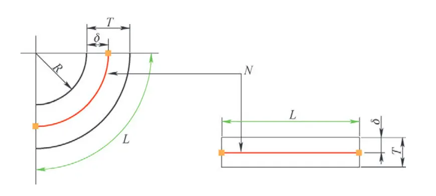
Neutral layer factor K = δ/T, Y = K × (π/2), the length of the bending zone L = (πR + 2YT)θ/180, the empirical coefficient a = L-2T. K = {a-2T + 2 (R + T) tan [(180-θ) × π/360]}×180/[( 180-θ)πT] – R/T.
When θ = 90°, K = (2R + a) × 180/(πTθ) – R/T. The unfolded length L = L1 + L2 + π(R + KT)(180-θ)/180-2(T + R) tan [(180-θ)π/ 360]. L1, L2 are for the fittings bending size, R is for the fittings bending radius of the inner circle, and T is for the plate thickness.
Bending parts hole edge distance
Pre-machined holes in the blank material: If the hole is located in the bending deformation zone, then the shape of the hole in the bending will be stretching deformation, which will also affect the size of the fittings after bending.
To avoid the distribution of holes in the bending deformation zone, it should generally be ensured that the distance b (the closest distance from the outer edge to the edge of the hole after bending) ≥ 3 times the thickness of the plate.
For elliptical holes parallel to the bending line, the distance between the edges of the holes should generally be ≥ 4 times the thickness of the plate to ensure bending accuracy and prevent deformation.
Suppose the holes must be distributed in the deformation zone to ensure precision. In that case, generally, the first processing of small holes is bending and then reaming to meet the requirements, but also, depending on the location of the bending process, hole punching or notching to transfer the deformation zone.
Bending straight edge height
For 90 ° bending, the straight edge height h ≥ 2t (t for the plate thickness) facilitates the workpiece’s formation.
If the design needs to bend the straight side of the height of h < 2t, the first to increase the height of the bending side, to be formed after bending and then processed to the required size; or in the bending deformation zone after the processing of shallow groove and then bending.
On the bending side with beveled bending parts, that is, the bending deformation area in the diagonal, the workpiece will be deformed after bending due to the low height of the straight line at the end of the diagonal.
Therefore, the minimum height of the bending side should meet h> 2t; otherwise, the height of the straight side of the bending parts should be increased, or the structure of the parts should be changed.
Bending direction of the bending parts
Determine the bending direction should try to make the blank blanking fracture zone on the inside of the bending parts to avoid the fracture zone within the micro-cracks in the outer tensile stress under the action of the expansion of the fracture.
If the parts’ structural limitations require positive and negative bending in both directions, they should try to increase the bending radius or use other process measures.
The anisotropy of the sheet material also has a certain effect on the bending deformation, especially because of its poor plasticity. In the case of the permit, the workpiece bending line should be perpendicular to the direction of the sheet material fiber. Otherwise, when the bending line is parallel to the direction of the fibers, the bending of the outside of the part can easily form cracks.
If you have to bend in multiple directions, the bending line should be made with the fiber direction at a certain angle.
The spring back of the bent parts
Bent parts of the spring back refer to the plastic deformation of the sheet material, which causes the bent parts to change shape and size when removed from the mold.
The degree of spring back is usually used after bending the actual bending angle of the workpiece and the mold bending angle to indicate the difference between the size of the spring back angle.
Factors affecting the rebound include the mechanical properties of the material, the relative bending radius, the shape of the workpiece, mold clearance, and bending pressure.
As more factors affect the rebound, the theoretical analysis of the calculation becomes more complex. In general, the greater the ratio of the radius of the inner corner of the bending piece to the plate thickness, the greater the rebound.
Bending parts of the rebound, at present, mainly through the mold manufacturers to design molds, to take certain measures to reduce the rebound, such as the lower mold to reserve the rebound angle, the use of 88 ° or 86 ° of the V-shaped angle, etc., or bending to increase the corrective pressure to solve the problem.
Selection of the upper mold for sheet metal bending dies
(1) the choice of the type of upper mold selection of what kind of upper mold is determined by the shape of the workpiece, because the bending process between the mold and the workpiece must not interfere with, for example, in the U-shaped bending, which should be based on the size of the three sides of the proportion of the selection of the appropriate upper mold.
Usually, if the bottom edge size is greater than or equal to the other two right-angled edges, the frame can be selected with the upper mold; if the bottom edge is smaller than the other two sides, the upper mold should be selected with a gooseneck.
To prevent bending parts and mold interference, which can result in parts deformation or scrap, you can use the AMADA bending machine bed display to simulate the bending of this accessory and detect whether the mold is suitable for the accessory’s bending and forming.
(2) the upper mold corner radius R selection of the outer corner radius of the workpiece is mainly determined by the lower mold V-groove width. At the same time, the upper mold corner radius R also has a certain impact.
The upper die corner radius R is generally taken with the same thickness or slightly smaller in the folding of duralumin and other plastic parts to prevent fractures or cracks; the upper and lower die corner radius and V-groove size are larger at the same time in the fittings of the design of the bending line at both ends of the stop-cracking groove.
(3) The choice of the angle of the tip of the upper die in addition to the 90 ° upper die, in the folding of large rebound SUS stainless steel, aluminum, or medium-thick plate, according to the size of the rebound of the material, can be selected 86 ° or 88 ° upper die and should be selected at the same time, the same angle of the lower die with its matching.
Selection of the lower die for sheet metal bending molds
(1) The lower die V-groove width selection V-groove width selection is mainly based on the thickness of the plate. The larger the V-groove width, the smaller the required bending pressure. Generally, the thinner the plate material is often taken as V = 6t, of which V is the lower die V-groove width; t is the thickness of the plate. Ordinary lower mold V-groove width and plate thickness of the selected Table 1.
Table 1 standard lower mold V-groove width and plate thickness of the selected
In addition, consider the size of the part bending. When the size is small, if the lower die V-groove width is large, the top of the sheet can not be bent with the V-groove shoulder contact force simultaneously; it will slide into the V-groove, failing to form.
(2) Selection of lower mold shape lower mold
The lower mold is generally divided into a single-slot lower mold and a double-slot lower mold. While the single-slot lower mold is flexible and convenient, the double-slot lower mold is more stable. The applicable lower mold is determined according to the actual situation.
In addition, the lower mold has some special shapes, such as the segment difference mold, crimp shoot flat mold, the folding arc of the elastic rubber lower mold, and so on.
(3) V-shaped groove angle of the lower die V-shaped groove according to the angle is divided into right angle lower die and acute angle lower die, acute angle lower die commonly used angle is 30 ° and 45 °, right angle lower die commonly used angle of 88 ° and 90 °, the standard angle of the lower die is 88 °, the choice is based on the nature of the material and the amount of spring back to determine.
When the material tensile strength and rebound amount are larger, such as stainless steel or thinner plate, 88 ° should be selected ° under the mold; ordinary mild steel, copper, and other softer materials can be selected 90 ° under the mold.
Factors affecting the rebound are analyzed as follows.
(1) related to the nature of the material. The size of the rebound amount of comparison for SUS> Al> SPCC is in the same mold and material thickness under the same conditions.
(2) in the same mold and material conditions, thin plate rebound > thick plate rebound.
(3) the same material bending arc radius R is larger, and the rebound amount is large.
(4) the more significant the bending pressure, the smaller the amount of rebound.
About offset bending
In the case of feasible, the workpiece should be placed as far as possible in the machine axis symmetrical bending so that the operation is more accurate than the workpiece offset bending and can avoid the adverse effects of the machine due to the bias load. If you do have to offset bending, it is recommended that the bending tonnage be not more than 30% of the total tonnage.
Bending common problems and solutions
(1) bending size does not meet the drawing requirements of the reasons for analysis and measures to solve Table 2.
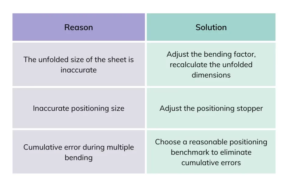
(2) The bending angle is too large or too small, which provides reasons for analysis and measures to address Table 3.
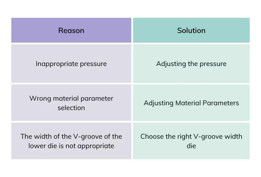
(3) Table 4 shows the inconsistent analysis of the bending angle and measures to address the reasons.
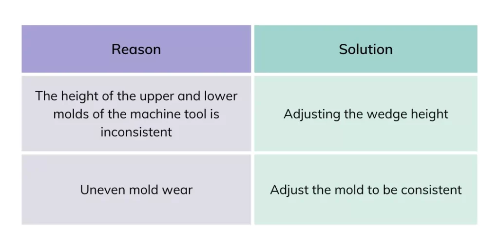
(4) bending size inconsistency in analyzing the causes and measures to address Table 5.
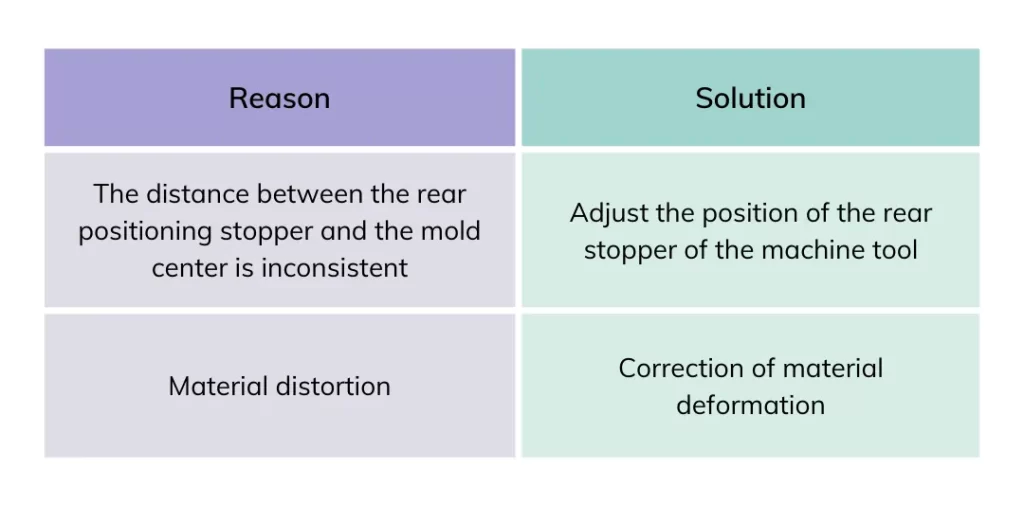
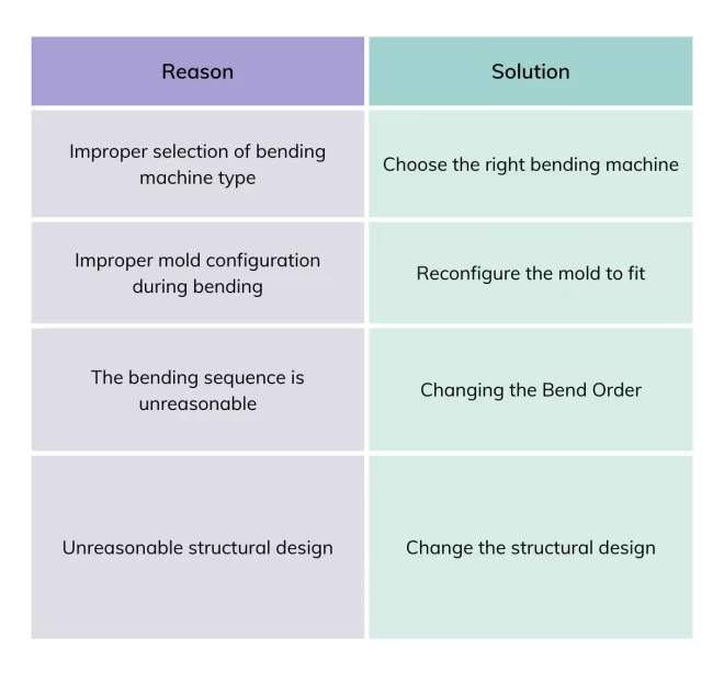
(5) Interference in parts processing, bending, and forming can not be fully completed analysis of the causes and measures to address Table 6.
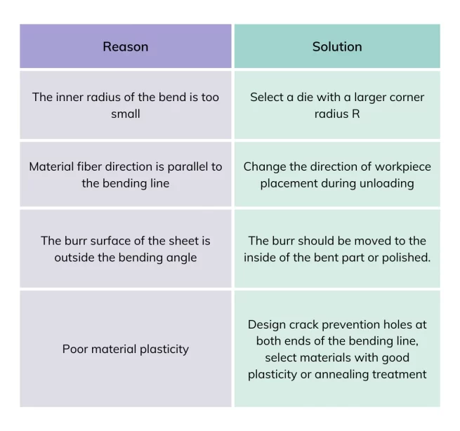
(6) The reasons for cracks at the corner of the sheet bends are analyzed, and solutions are shown in Table 7.
Conclusion
This paper is mainly from the perspective of the bending process of sheet metal bending process and related process parameters were analyzed, focusing on the bending process of sheet metal bending how to calculate the unfolding size and bending compensation value, how to reasonably select the mold, to determine the size of the bending force and the bending process of the common problems that arise in the answer, with some reference.