How to design a circular arc core pulling injection mold?
In the plastic shell mold design session, it often faces the challenge of various circular arc-type designs, which undoubtedly increases the complexity of the design.
In order to overcome this challenge, the article on a cylinder-driven rack and pinion circular arc core extraction injection mold as an example, a detailed discussion of the structural design theory calculation and computer-aided engineering simulation of the mold design.
Arc core pulling structure
1. Slider linkage structure
Slider linkage structure plays an important role in the arc core extraction process. Take a specific part as an example; its internal design needs to shape a circular cavity.
To meet this specific need, the mold must be able to achieve one end along the arc path, the other end along the straight line for core extraction.
When the mold is opened, the piston in the hydraulic cylinder moves the arc-shaped core with the help of tie rods and connecting rods.
The precise constraints of the arc track ensure that the arc core strictly follows the preset arc trajectory, thus ensuring the accuracy of the arc core extraction.
At the same time, the slider at the other end will be precisely guided by the inclined guide column to carry out the downward movement to complete the core extraction operation of the side cores.
2. Rack and pinion structure
The rack-and-pinion structure allows for efficient arc core extraction. For example, a specific plastic part with two circular holes requires a specially designed structure to accomplish the circular core extraction task.
In this design, the arc cores are securely mounted on arc slides tightly coupled to the gear shaft. For this operation, the rack is secured to the tilting slide.
When the mold is opened, the slanting column drives the slanting block and the rack and pinion together downward. During this action, the rack drives the gear shaft, the arc slide, and the arc core to rotate so as to complete the arc core extraction action accurately.
3. Cylinder-driven floating slide structure
In the injection mold design, a cylinder-driven floating slider core extraction structure is undoubtedly an efficient solution due to the complex structure and the need for multidirectional core extraction of plastic parts.
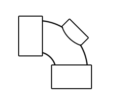
Take the tee part as an example, which is characterized by the need to complete the core pulling action in three different directions, including two linear directions and one circular arc direction, as shown in Figure 1.
The complexity of this requirement makes the traditional core pulling structure difficult to handle, while the cylinder-driven floating slide core pulling structure can perfectly solve this problem.
Specifically, the structure realizes core extraction by precisely controlling the movement of multiple cylinders. Cylinders 1 and 3 control the linear core pulling of side cores 2 and 4 in the A and B directions, which is relatively straightforward to control.
However, the realization of circular core pulling is more subtle. After cylinder three has driven the side cores 6 for the initial linear extraction, the necessary space is made available for the circular extraction.
Subsequently, by pulling the connecting rod 7, the structure forces the arc core five into motion.
Due to the special connection between the arc core and the connecting rod and the geometrical constraints of the molded part cavity, the arc core cannot move in a straight line but can only rotate with a specific connecting pin in the center, thus achieving a precise arc core extraction.
The structure of cylinder-driven floating slide core extraction is shown in Figure 2.
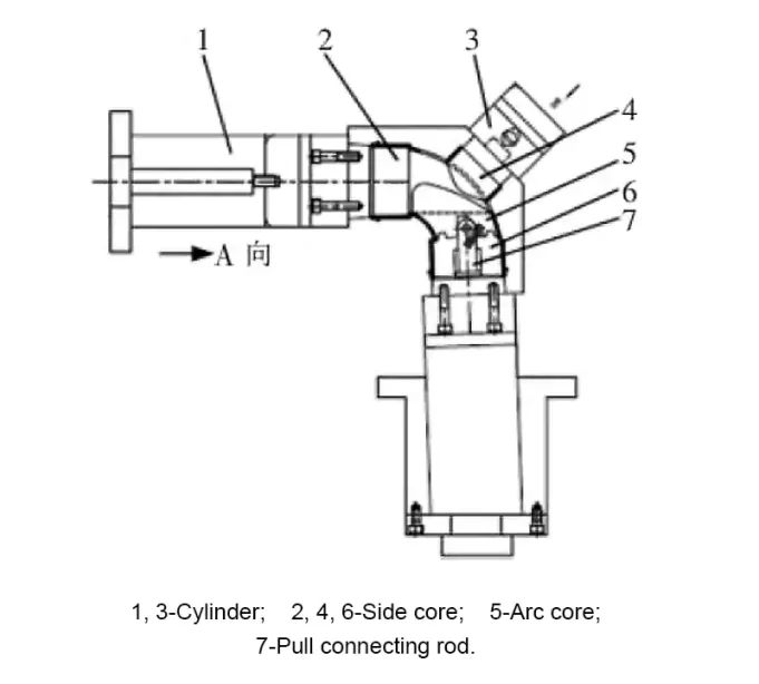
During the reset process, the cylinder plays a key role in pushing the side core 6 upward until it contacts the arc core 5, thus pushing it to reset.
This design’s ingenuity allows complex core pulling movements to be accomplished in a limited core pulling space, greatly increasing the mold’s flexibility and applicability.
However, it also places high requirements on the cylinder’s control precision and the structure’s manufacturing precision. It needs the support of a special cylinder, and the core pulling stroke is somewhat limited.
4. Floating slide core pulling structure
Floating slider core pulling structure is a widely used core pulling structure in injection mold design. Its working principle mainly relies on the synergistic effect of the spring and the tie rod. The floating slide core pulling structure is shown in Figure 3.
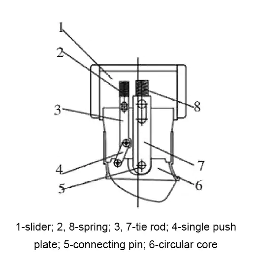
At the beginning of the molding process, the arc core 6 remains stationary due to the action of springs 2 and 8. As slide 1 moves upward, the spring gradually releases its energy until it completely relaxes.
At this point, the tie rods 3 and 7 come into play, driving the arc core to rotate around the connecting pin 5, realizing the arc core extraction.
This design’s unique feature is the adaptive adjustment function, which can effectively respond to possible motion interferences.
In the event of interference, the spring 8 plays a key role, allowing the drawbar 7 to float flexibly to compensate for the interference, thus ensuring a smooth and unobstructed core extraction.
In the reset phase, slider 1 first moves downwards, followed by the restoring force of spring 8, which drives the arc slider to a precise reset.
5. Pendulum structure
As a simple and efficient arc core pulling structure, the pendulum structure occupies an essential position in the design of injection molds. Its working principle is mainly based on the interaction between the connecting rod and the pendulum, and the pendulum structure is shown in Figure 4.
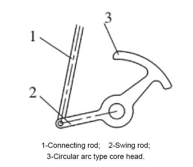
The upper end of connecting rod 1 is tightly connected to the moving mold by means of a pin, while the lower end is connected to pendulum 2 utilizing a pin. The pendulum itself is also fixed to the static mold using pins.
During mold opening, the connecting rod 1 drives pendulum 2 to rotate around the rotary center of the moving mold, thus realizing the arc core extraction.
When the mold is closed, the movement of the moving mold forces the connecting rod to drive the pendulum to reset.
This structural design’s advantages are its simplicity, ease of manufacture, and maintenance. However, due to the limitation of its working principle, the core extraction direction of the arc side core is subject to certain constraints.
Therefore, to ensure the structure’s applicability and reliability, the geometry of the molded part and the core extraction requirements must be fully considered during the design process.
Design content of circular arc core pulling injection molds
1. Plastic shell design
The basic structure of the plastic shell usually includes the outer wall, inner wall, reinforcement, mounting holes, and connection parts.
(1) Outer wall.
It is the primary appearance part of the plastic shell, and its design should consider the aesthetics, durability, and the use of the product environment. For example, plastic shells for outdoor use need to consider UV and weather resistance, while shells for indoor use pay more attention to appearance and feel.
(2) Inner wall.
It mainly supports and fixes the internal components. Its structural design needs to ensure sufficient strength and stability to prevent damage to the internal components during transportation and use.
(3) Reinforcement bars.
Reinforcement bars improve the shell’s overall rigidity and impact resistance, reducing the risk of deformation and damage. The design of the reinforcing bars needs to consider their distribution and thickness to achieve the best reinforcing effect.
(4) Mounting holes and connection parts.
The design of these parts needs to consider the ease and solidity of assembly. For example, the size and location of mounting holes need to be precisely controlled to ensure a tight fit with other parts.
In terms of material selection, plastic housings are usually made of plastic materials with good processability, mechanical properties, and weather resistance. These materials are not only easy to process and mold but also can meet the various performance requirements of the product in use.
2. Mold parting surface design
Mold parting surface refers to the mold in the closure, two or more mold parts in contact with each other.
The design of the parting surface directly affects the molding quality of the plastic shell and mold life.
(1) Selection of parting surface.
Parting surface should be selected as far as possible in the appearance of the plastic shell surface or non-important functional surface, in order to avoid the important parts of the joint marks.
The design of the parting surface should also consider the mold’s machining and assembly difficulty to ensure the mold’s manufacturing accuracy and stability [6].
(2) Mold structure requirements.
The mold’s structure should be compact and reasonable to facilitate processing, assembly, and maintenance. The cooling system should be reasonably designed to ensure that the plastic shell can be uniformly cooled during the molding process to avoid thermal stress and deformation.
In addition, the exhaust system of the mold is crucial, as it can help remove the gas in the mold cavity to avoid defects such as bubbles and burning.
3. Gate Optimization Design
(1) Selection of gate location.
The gate should be as close as possible to the thick-walled part of the shell to reduce the melt’s flow distance and improve the filling effect.
The gate should not be set on the shell’s important appearance surface to avoid affecting the product’s aesthetics.
Also consider the plastic’s flow path to ensure that the plastic can evenly fill the mold cavity.
(2) Design of gate shape.
The shape of the gate should be designed according to the plastic’s fluidity and the shell’s structural characteristics. Common gate shapes include fan, ring, point gate and so on.
A reasonable gate shape can ensure that the plastic fills the mold cavity evenly and quickly and reduce defects.
(3) Optimization of gate size.
The gate size directly affects the flow rate of plastic and molding pressure. Too large a gate will cause the plastic to flow too fast, making it easy to produce jet marks, bubbles, and other defects.
Too small a gate will increase the molding pressure, affecting the dimensional accuracy and surface quality of the product.
Specific design should be based on the type of plastic, shell structure, and molding process requirements to determine the reasonable size of the gate.
(4) The design of the gate cooling system.
To ensure that the plastic shell can be quickly and evenly cooled and cured, an effective cooling system should be set up near the gate.
This can be realized by arranging cooling waterways around the gate or using materials with good thermal conductivity.
A reasonable cooling system can improve the product’s molding quality, shorten the molding cycle, and increase production efficiency.
4. Design of the circular core pulling transmission structure
The arc core drive structure plays a central role in the mold design, and its main function is to ensure the precise molding of the side holes or side recesses of the plastic shell.
The following points must be considered when designing the arc core pulling transmission structure.
(1) Transmission mode selection.
The circular arc core pulling transmission structure can be used with various transmission methods, including mechanical, hydraulic, and pneumatic transmission.
When selecting specific transmission methods, the stability, reliability, and cost-effectiveness of the transmission must be fully considered to ensure that the selected program can meet the actual needs.
(2) The design of the circular arc core.
To ensure molding accuracy, its shape and size must be strictly customized according to the shape and size of the side holes or side recesses of the plastic shell.
The material and surface treatment of the circular arc extractor are also aspects that cannot be ignored; they directly affect the structure’s wear resistance and service life.
(3) Layout of transmission structure.
A reasonable layout not only facilitates processing, assembly, and debugging but also ensures that the various components in the transmission structure are closely matched, thus achieving the transmission’s accuracy and stability.
(4) Lubrication and cooling of the transmission structure.
The moving parts in the transmission structure must be adequately lubricated to reduce friction and wear. In the application of high-temperature molding of plastic shells, the transmission structure also needs to be effectively cooled to prevent deformation or damage due to the high temperature.
Conclusion
The article puts forward various optimized design solutions through an in-depth discussion of the design of circular arc extraction core injection molds.
Through a detailed analysis of the slider linkage structure, rack and pinion structure, cylinder drive structure, floating slider core pulling structure, pendulum structure, and other circular arc core pulling methods, for the design of injection molds to provide a richer and more flexible choice.
Meanwhile, innovations in plastic shell design, mold parting surface design, gate optimization, and circular arc core extraction drive structure design not only improve the mold’s practicality and reliability but also provide new ideas for optimizing the injection molding process.
This research result is significant in promoting the progress of injection mold design technology and the development of the injection molding industry.