How to design a reverse hot runner injection mold design?
In recent years, with the booming development of the injection molding industry, a variety of plastic electronic products have become increasingly widely used in daily life. To accommodate the various product designs, the plastic mold structure has become more complex and diverse.
As an office supplies member, I know that the upper shell of a paper shredder has unique product attributes in the shell mold. The main reason is that there is a narrow paper inlet on the mold, and as the overall upper shell (as shown in Figure 1), it is tough to choose the location of the inlet in the mold design.
In this case, to solve the problem of sprue marks on the surface of the plastic part when designing the mold, a hot runner mold with a complex inverted structure and rear mold inlet was created especially for the paper shredder, where the whole upper case is all appearance surface.
The ejector action is completed by designing the mechanical pulling hook. During the production process, the mold mechanism operates smoothly, and the quality of the plastic parts is excellent and meets the design requirements.
To solve the problem of gate marks on the surface of the plastic parts, we designed a pair of complex, inverted-structure injection molds, which we hope to use as a reference for our peers.
Structure of the plastic part and process analysis
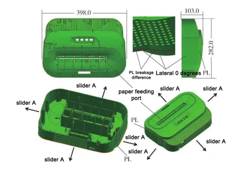
As shown in Figure 1, the structure of the plastic parts:
Shredder upper shell plastic parts from the front similar to a regular rectangle, four corners of R40mm;
From the side view, the top part is a curved shape with bipolar steps, the external dimension is 398 mm×282 mm×103 mm, and the mass is about 800 g, a medium-large plastic part. The internal bone position of the part is more, and it is difficult to mold;
The molding direction around the outside is at a right angle, the surface requires etching, and there are heat dissipation holes on the two surfaces, so the molding direction can be inverted. Therefore, it is necessary to design a four-side slider core pulling mechanism to solve the molding problem.
The material of the plastic parts is acrylonitrile-styrene-butadiene copolymer (ABS), fire rating V-0. After adding flame retardant, the material is more sensitive to temperature, and it is easy to trap gas and carbonization of the material;
The average wall thickness of the main body is 2.8 mm, with uniform wall thickness and 1.6 mm rib thickness, which is in line with the design specification of injection molded parts and is not easy to produce shrinkage phenomenon;
The plastic parts’ surfaces, except for the position of the middle paper inlet, all have an A-grade appearance, and the design of the glue inlet is complex.
Overall design of mold structure
1. Pouring system design
The size of the plastic parts of the upper case of the paper shredder is medium-large, the surface of the A-level appearance is highly required, and the traces of sprue are not allowed, the structure is complicated, the rib and column are deep and many, especially the shape of the plastic parts is in the shape of a two-stage step, and one side of the mesh structure, which is easy to cause the filling difficulty.
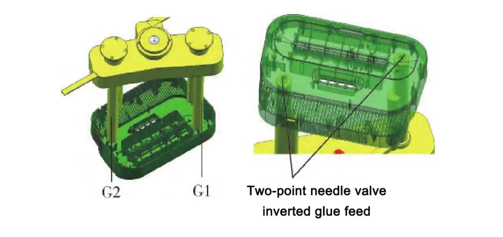
The mold uses the needle valve hot runner two-point inverted from the rear mold into the glue way, successfully solving the molded part’s surface, which does not allow traces of the problem.
Due to the inverted structure, the length of the nozzle is more than one times longer than that of the conventional feeding glue from the front mold, and each nozzle is designed with two heating sections and two temperature control sections to avoid the temperature difference between the nozzles is too large, as shown in Fig. 2.
2. Four weeks assembling slide core pulling mechanism
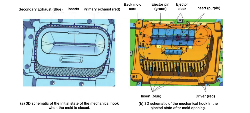
Fig. 3 shows the 3D schematic diagram of the four-side slider core pulling structure of the rear mold (fixed mold side), (a) is the closed state of the slider core pulling, (b) is the completed state of the slider core pulling.
The molded part is surrounded by a 0-degree demolding angle, and the surface appearance requires etching YS20007. In addition, there are inverted holes in slider A and slider B, and the four-side slider core extraction structure can ensure that the part does not deharm when it comes out of the mold.
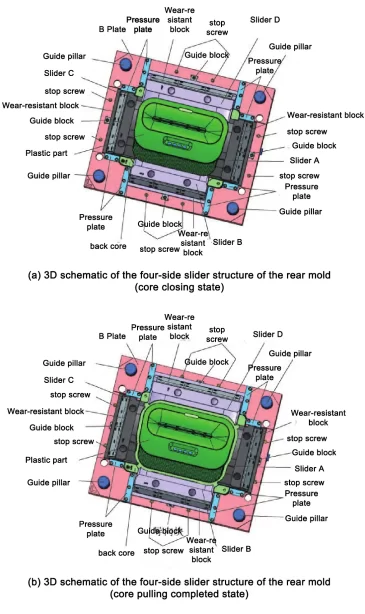
The four sliders A/B/C/D are assembled to form the peripheral glue surface of the plastic part; the pressure plate fixes each slider.
A guide block structure is set in the middle to ensure the matching precision between the sliders, the slider is driven by the tilt pin when the mold is opened, and the spring 22 (shown in Fig. 4) provides the auxiliary core extracting power and maintains the sliders’ relative position to ensure a smooth reset when the mold is closed. The limiting screws fix the stroke of the sliders.
Wear-resistant blocks are provided on each slider to facilitate maintenance in the later production process; the shovel base is left in the original body through the A-plate for better strength.
3. Ejector and reset structure of the mold opening hooks
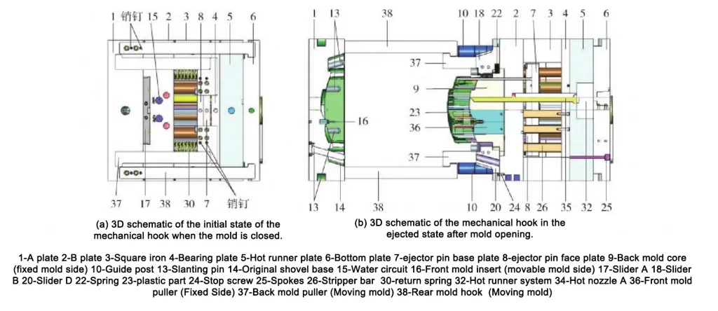
The case is a reverse mold, i.e., the front mold is moving, and the rear mold is fixed. The ejector mechanism of the injection molding machine cannot be used for molding production.
Instead, a mechanical hook is set on the ejector plate (fixed mold side) and the front mold (moving mold side). When the mold is opened, the ejector plate is moved by the mechanical hook with the mold opening tension of the injection molding machine to complete the ejector operation;
When closing the mold, use the spring on the return pin to complete the reset of the ejector plate.
The mold opening and closing process requires no additional settings, is simple and reliable, and has high production efficiency.
When designing the hooks, attention should be paid to the balance of the four hooks to ensure that each hook is subjected to a uniform force during molding. In addition to the dimensional requirements, the assembly must be fitted with pins to set the position.

4. Design of Bone Position Inserts and Mold Exhaust System
The plastic parts are made of ABS, V-0. After adding flame retardant, ABS melts produce more gas, such as lousy exhaust, and can not achieve excellent appearance quality.
The mould design in the front model cavity (moving mold side) is set up around the plastic part of the whole circle of the two-stage exhaust system.
The secondary exhaust is 10 mm wide and 0.3 mm deep;
The first-stage exhaust groove is set every 20 mm in the whole circle, with a width of 4 mm and a depth of 0.02 mm, to ensure that the gas can be discharged quickly and effectively;
On the rear mold (moving mold side), the bone inserts, ejector block, barrel, and ejector pin are used to assist the exhaust to prevent the trapped gas from causing poor molding so that the molded parts can obtain excellent appearance and molding quality.
5. Mold cooling water circuit design
Fig. 6 shows the schematic diagram of the cooling water circuit. There are seven straight water circuits on the front mold (moving side), which are uniformly distributed, and each water circuit has four water wells.
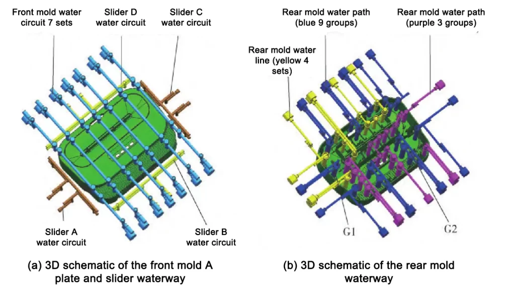
The sliders around the sides are each equipped with a separate water circuit, and a total of 11 water circuits in the front mold are evenly distributed around the entire shape of the part to ensure uniform cooling of the entire front mold (moving mold);
The rear mold (fixed mold side) is equipped with a total of 16 cooling water lines, each of which is equipped with a water well, including around the hot nozzle, to prevent the hot nozzle position from localized high temperature and bright marks on the surface;
The excellent design of the water circuit can reduce the surface temperature difference between the cavity and the core, allowing the plastic part to shrink uniformly during molding.
This reduces deformation and warpage and shortens the molding cycle, improving production efficiency.
In this case, the molding cycle is 56 s, 20% higher than the design value, with stable production and excellent quality.
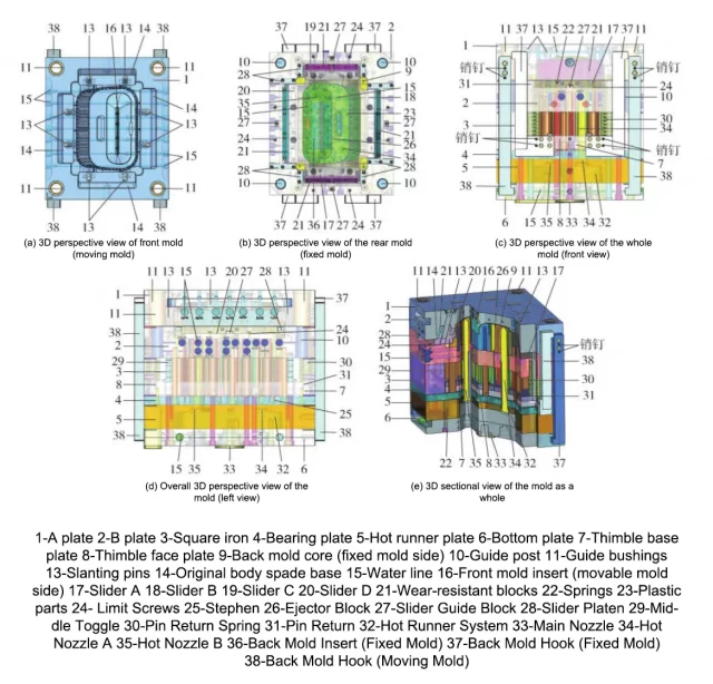
6. Overall mold structure
The mold adopts the layout of one mold and one cavity because the surface of the appearance can not be set up to feed the glue, using the rear mold inverted structure hot runner two-point glue feeding method.
As shown in Fig. 1(a) and (c), the surface has a 0-degree mold release slope on four sides and inverted buckles on two other sides. The mold is released by pulling the four-sided assembly slider core.
The non-standard customized inverted mold frame size 600 mm×700 mm×646 mm, the maximum external dimensions need to be added 40 mm on each side of heaven and earth to open the thickness of the hook, the thickness of the mold to add 10 mm in the direction of the heat insulation board, the total size of 600 mm×780 mm×656 mm, weighing about 1,900 kg, the volume of the mold belongs to the medium-large size specifications.
The overall structure of the mold is shown in Fig. 7.
7. Mold-working process and test mold problem point analysis and improvement countermeasures
Mold working process:
(1) Closing the mold, the ejector plate is firstly reset under the action of spring 22, and then the four side sliders A/B/C/D are reset to close the mold, and the mold closing is completed;
(2) plastic melt through the injection machine nozzle into the mold a main injection nozzle 33, through the hot runner system 32, two hot nozzles 34 and 35 into the cavity, holding pressure, cooling to complete the first molding;
(3) Open the mold, oblique pin drive slider A/B/C/D to complete demolding; mechanical hook drive ejector plate to complete ejection;
(4) Pick up the parts. After the mold opening, the plastic parts can be picked up manually or by robot. This completes the molding cycle, which is repeated to implement production.
The first trial mold appeared in some areas of the top of the white top high phenomenon. After analyzing the results, they are as follows: Figure 8 shows the plastic parts tendons are more profound. Save the mold, there is room for improvement, resulting in the ejection of the immense force of the white top high phenomenon.
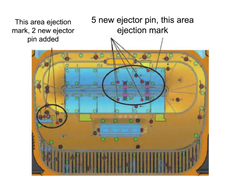
Improvement countermeasures: local increase ejector pin, strengthen the mold core polishing, especially for the rib position, which is particularly important.
After changing the mold, the high-top white top can be solved, and the quality of the plastic parts is good, which aligns with the requirements of mass production.
Conclusion
(1) Through the inverted mold structure, hot runner two-stage rear mold into the glue way to successfully solve the surface of the plastic parts can not enter the glue problem;
(2) Solve the problem of 0-degree demolding angle on the side of the part and the problem of inverting the mold utilizing four-side slider core pulling;
(3) Using the role of the injection molding machine to open the mold pulling force, using the opening hook structure to solve the problem of ejecting the plastic parts after the mold is installed upside down, this solution is more efficient than the additional increase in the cylinder ejector;
(4) Plastic parts with many bone bits are difficult to mold, through the way of insertion to solve the molding problem of trapped gas burnt easily.