How to use the dividing head?
The indexing head is one of the main accessories of the milling machine, and many parts, such as gears, clutches, spline shafts, and tool openings, need to be indexed using the indexing head when milling.
Usually, in the milling machine, the indexing head has a simple indexing head, universal indexing head, automatic indexing head, and so on. Among them, the universal indexing head is more widely used.
Universal indexing head structure and transmission system
Indexing head (Figure 1) spindle 9 is hollow, both ends of the Morse 4 taper hole, the former taper hole used to install the top with a dial, the back of the taper hole can be installed human heart axis, as differential indexing or as a straight line for the distance shifted indexing as well as the processing of small lead helical surface when the installation of hanging wheels with.
The spindle has a locating cone on the outside of the front of the spindle, which is used to fit the flange of the connecting disk of the three-jaw self-centering chuck.
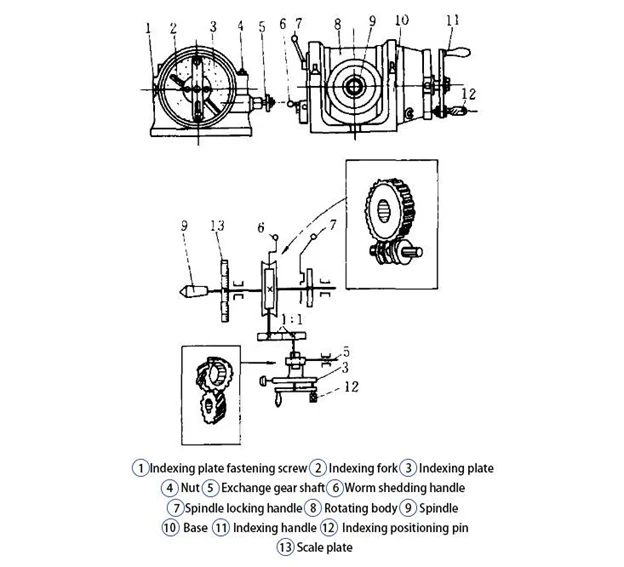
The spindle rotates with the rotating body 8 in the circular guideway of the indexing head base 10. Therefore, in addition to the spindle installed into a horizontal position, but also in the -6 ° ~ 90 ° range of arbitrary tilt, before adjusting the angle of the base should be loosened against the spindle back end of the two nuts 4, adjusted and then be tightened.
The front end of the spindle is also fixed a dial 13, can be rotated with the spindle. The dial has a scale of 0°~360°. The dial has a scale from 0° to 360° and can be used for direct indexing.
There are several circles of positioning holes evenly distributed on the circumference of the indexing disk 3, and there is an indexing disk fastening screw one on the left side of the indexing disk to fasten the indexing disk.
There are two handles on the left side of the indexing head. One is the spindle locking handle 7, which should be loosened when indexing and closed after indexing.
The other is the worm shedding handle 6, which disengages or engages the worm and worm gear. The engagement clearance of the worm and worm gear can be adjusted with an eccentric bushing.
An indexing handle 11 is on the right side of the indexing head. When the indexing handle is rotated, the spindle is rotated by a pair of straight-toothed cylindrical gears with a transmission ratio 1:1 and a pair of worm gears with a transmission ratio 1:40.
In addition, on the right side of the indexing disk, there is an exchange gear shaft 5 for mounting an exchange gear, which is connected to the indexing disk, which is empty set on the indexing handle shaft by a pair of helical gears with a speed ratio of 1:1.
There are two locating keys fixed in the grooves below the indexing head base 10, which can be fitted to the T-shaped grooves of the milling machine table so that when the indexing head is mounted, the spindle axis is made accurately parallel to the longitudinal feeding direction of the table.
Second, indexing method
A single-type indexing method from the indexing head of the transmission system can be seen: indexing handle turn 40 spindle turn 1, that is, the transmission ratio of 1:40. “40” is called the number of fixed indexing heads.
Various types of universal indexing heads basically use this number.
Assuming that the workpiece is equivalent to a fraction of z, each indexing spindle needs to turn a 1/z circle, that is, the single-type indexing method formula.
n=40/z
In the formula
n — number of revolutions of the indexing handle
z — equal parts of the workpiece
Example: milling straight-toothed cylindrical gear, the number of teeth z = 12, the number of revolutions per indexing handle.
n=40/z=40/12=3 (8/24)
After milling a tooth, the indexing head handle swings three revolutions, and then eight hole spacings on a hole circle of 24.
The single-type indexing method can also be used directly from the single-type indexing table in standard machining manuals to find the calculation results.
Differential indexing method
The differential indexing method is used to process the single-type indexing method, which can not index spur gears and general parts.
This indexing method is characterized by the use of hanging wheels to the indexing head spindle and side shaft coupled together and loosening the fastening screws of the indexing disk (Figure 2), so that when the indexing handle rotation at the same time, the indexing disk with the indexing handle in the opposite direction or the same direction of rotation so that the actual number of revolutions of the indexing handle is the indexing handle relative to the number of revolutions of the disk and the disk itself the number of revolutions of the sum.
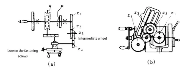
Calculation formula.
Number of revolutions per indexing handle
n=40/z1
Transmission ratio i=40(z1-z)/z1
where z1 — the hypothetical number of workpiece parts
Points to note for operation.
Take the assumption that the equivalent number of z1, in principle, the value of z1 as long as the single indexing can be carried out, whether it is greater than or less than the actual equivalent number of z can be.
But practice has shown that when using z1 < z2, indexing disk and indexing handle to the opposite direction to avoid the impact of the drive system gap on the indexing.
Calculate the number of indexing handle revolutions and determine the number of hole turns used according to the assumed equivalent fraction z1.
Calculate the hanging wheel according to the formula and determine the number of intermediate wheels table (Table 1)
Example: There is a straight-toothed cylindrical gear, z = 111, to find in the milling of the indexing head handle rotation n and transmission ratio i is equal to how much? Assuming that the number of teeth of the selected gear z1 = 120
i=40(z1-z)/z1=40(120-111)/120=80×90/60×40
n=40/z1=40/120=22/66
Two pairs of exchange gears are used, with 80 and 90 being the active wheels and 60 and 40 being the passive wheels.
Assuming that gear z1>z2, the handle and the indexing dial rotate in the same direction, the two exchange gears do not add an intermediate wheel. For each tooth milled, the indexing dial handle is turned into 22 hole pitches around the circumference of the 66-hole circle.
Differential indexing methods can also be used directly from the differential indexing table in standard machining manuals to find the calculation results.
Approximate indexing method
The approximate indexing method for processing single-type indexing can not be indexed helical or straight bevel gears.
This indexing method has an inevitable error and can only be used when the workpiece precision requirements are not high.
Now, take milling z = 93 as an example to illustrate the approximate indexing method of the formula process.
First, the indexing head handle is used to shake the number of revolutions according to the single indexing method.
n=40/z=40/93
As this number can not be simplified, the indexing disk is not 93 holes on the hole ring and can not be divided. If an arbitrary hole circle is selected on the indexing dial, such as N=59, then each time the handle should be shaken during indexing.
(40/93)x59=25.37634
Because the resulting number is small and can not shake the handle, 25.37634 can be expanded by a multiple, trying to make it close to an integer; now, this number will be expanded by 8 times.
25.37634×8~203.01075
This number is close to 203 integers so that it can be 203 holes in 59 holes in the hole spacing on the ring for indexing. The handle should be the number of revolutions: n = 203/59 = 3.01075
n=203/59=3(26/59)
After milling a tooth, the handle swings three revolutions, and then other 26-hole pitches are turned on the hole circle of 59 holes. Because the number of holes is multiplied by 8, the number of holes shaken at this time is the original number of holes to be shaken 8 times the number of holes, that is, after milling the first tooth, and then milling is the ninth tooth, so that continuous, it can be all the teeth of the workpiece milling.
So, the approximate indexing method formula should be
n = 40NM
In the formula
N – – the number of selected indexing disk hole ring hole
M – the expansion of the number of times (jump teeth)
Approximate indexing methods can also be found in common manuals.
Angle indexing method
The angle indexing method is another form of single-type indexing method, but the basis of calculation is different. The single-type indexing method is based on the workpiece equivalent fraction z as the basis for calculation. In contrast, the angle indexing method is based on the workpiece’s need to turn the angle 0 as the basis for calculation. So, there are some differences in the specific calculation.
From the structure of the indexing head, it can be seen that the indexing handle shakes 40 turns, and the indexing head spindle drives the workpiece to turn a turn, that is, turn 360 °. That is, the indexing head handle to turn a turn, the workpiece only turn 360 ° / 40 = 9 °, according to this relationship, it can be derived.
n=0/9°
Where 0 – is the angle of equal parts of the workpiece. Example: In a shaft milling two keyways, the angle of 77 °, how should it be indexed?
n=77°/9°=8(5/9)=8(30/54)
The indexing head handle turned eight turns and then, in the 54-hole ring, turned over 30-hole spacing.
Similarly, the angle indexing method can be found in standard manuals.
Linear shift indexing method
The linear displacement indexing method is suitable for processing high-precision racks, straightedge scribe lines, etc., and other points shift distance.
This indexing method is the central axis of the indexing head or side axis and longitudinal table screw connected with a hanging wheel shifting distance as long as the rotation of the indexing handle through the gear drive so that the table for accurate shifting distance. There are two commonly used linear shifting methods.
(1) spindle hanging wheel method this method is the first in the indexing head spindle after the taper hole inserted into the installation of hanging wheel mandrel, and then in the spindle and the longitudinal screw mounted between the hanging wheel (Figure 3), when the rotation of the indexing head handle, the movement will be transmitted to the longitudinal screw through the hanging wheel, so that the table to produce shift distance.
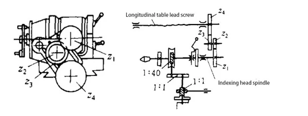
Since the motion is decelerated by a 1:40 worm gear, it is unsuitable for spindles with significant intervals of scribing, but the accuracy of the spindles is very high.
Calculation formula for hanging wheel
40S/nP=z1z3/z2z4
In the formula
S – workpiece distance per frame
P – milling machine longitudinal table screw pitch
It must be noted that n should be taken between 1 and 10.
Example: In the X62W milling machine with F1125 indexing head scribing: workpiece distance per cell S = 0.95mm, the number of indexing handle rotations and the number of teeth of the hanging wheel
Take the indexing handle rotation n = 4.75
40S/nP=(40×0.95)/(4.75X6)=(80×50)/(30X100)
The hanging wheel for z1 = 80, z2 = 30, z3 = 50, z4 = 100, indexing handle each indexing should be in the 24-hole circle turned 4 times and 18 hole distance.
(2) Side-shaft hanging wheel method of this method is in the indexing head side shaft and table longitudinal drive between the screw-mounted hanging wheel (Figure 4) because the movement does not go through the 1:40 worm gear transmission, so it is suitable for the interval of the more significant shift distance.
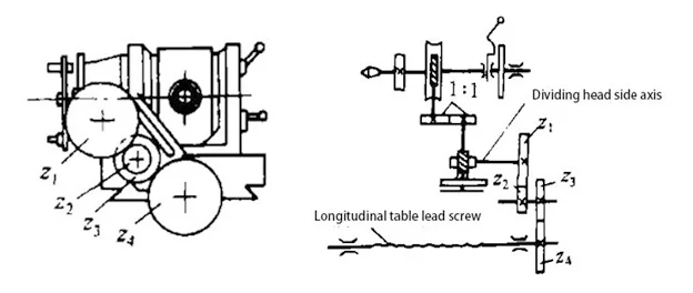
Hanging Wheel Calculation Formula
S/nP=(z1z3)/(z2z4)
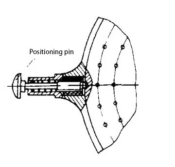
Due to the reason of the drive structure of the indexing head, using the side-shaft-hanging-wheel method, the positioning pin of the indexing handle cannot be pulled out during indexing, and the fastening screw of the indexing disk should be loosened to rotate together with the indexing disk.
To correctly control the rotation of the indexing handle can be divided into the fastening screw of the disk, modified for the side of the positioning pin (Figure 5), and in the indexing disk on the outside of the circle drilled a positioning hole in the indexing, the left hand to pull out the side of the positioning pin, the right hand will be divided into the indexing handle together with the indexing disk together with the rotation, when shaken to the predetermined number of revolutions, relying on the role of the spring, the side of the positioning pin will be automatically popped up in the positioning holes.
Example: A rack is milled on an X62W milling machine using an F11125 indexing head with a travel distance of S=6πmm at a time. Find the number of revolutions of the indexing head handle and the number of teeth of the hanging wheel.
Take the number of indexing handle revolutions n=3.
S/nP=6π/3X6=(6X22/7)/3X6=22/21=(4X5.5)/(3X7)=(80X55)/(60X70)
The hanging wheel is z1=80, z2=60, z3=55, z4=70, and the indexing handle should be shaken 3 times for each indexing.
Conclusion
Although the indexing head is rarely used in machining now, it is still a good mechanical learning tool because it demonstrates fundamental principles of angular division and precision.
Understanding how to operate an indexing head helps learners grasp the basics of gear cutting, slotting, and creating symmetrical patterns, which are essential skills for mechanical engineering and machining.