Mold Design Case: UAV Camera Lens Cover Mold Flow Analysis and Injection Mold Design
The increasing functions and types of UAVs have placed more demands on the design and manufacturing methods of various parts and components in the UAV industry.
Traditional mold development is based on workers’ production experience in designing mold structures and selecting mold parameters, which requires repeated mold trials and parameter modifications, resulting in longer development cycles and increased design costs.
Therefore, more and more designers apply CAE analysis software Moldflow to develop and design robot-related molds.
Engineers use Moldflow software to conduct mold flow analysis on the plastic parts of the upper cover of a drone with high requirements on product appearance, optimize the casting system and injection process parameters through mold flow analysis, and finally complete the design of the injection mold of the product, which effectively reduces the cost of product development and production.
Acrylonitrile-butadiene-styrene terpolymer (ABS) is highly strong, tough, easy to process and mold, and has a high surface gloss. It is widely used in many fields, such as aerospace, building materials, and machinery.
ABS can be used as the molding material for the lens cap of the UAV camera. Its excellent mechanical properties can produce a higher-quality lens cap, thus protecting the safety of the UAV camera lens. The higher surface gloss and easy processing properties of ABS can ensure the high-quality appearance of the lens cap product requirements and production efficiency.
This experiment on the drone camera lens cap process analysis, the use of Moldflow software on the parts of the gate position, cooling system, molding window, and warping deformation of a series of mold flow analyses, while the results of the mold flow analysis to verify; combined with the results of the mold flow analysis and the parameters of the molded parts to select the model for the MA900/260 injection molding machine, and its clamping force and other significant parameters for verification; based on the simulation analysis and calculation results, the ABS lens cap can be used to protect the safety of the drone camera lens. Based on the simulation analysis and calculation results, the structural design of the injection mold for the lens cover is completed.
The whole design process realizes the co-design of numerical simulation software, which improves the efficiency and reliability of the mold design, reduces the number of mold trials and repairs, and dramatically shortens the product design cycle.
Drone camera lens cap process analysis
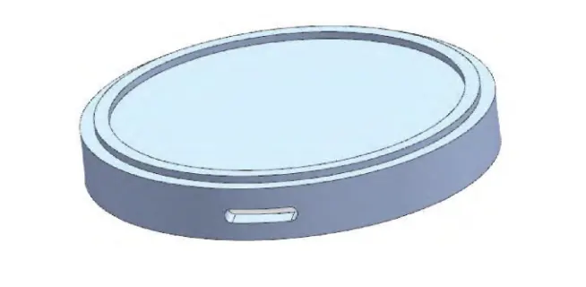
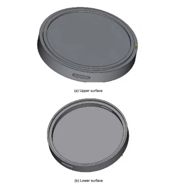
The lens cap of a UAV camera is a thin-walled cylindrical plastic part, and its three-dimensional model is shown in Figure 1. The dimensions are 56.0mm×56.0mm×8.5mm, with an average wall thickness of 1.5mm. The shape structure is relatively simple, but there is a through-hole on both sides, so it is necessary to set up a side core extraction mechanism to realize lateral parting.
The molding material is ABS, with a density of 1.02~1.05g/cm³, which has better mechanical properties and higher impact strength and flexibility than other plastic materials.
Moldflow analysis based on Moldflow
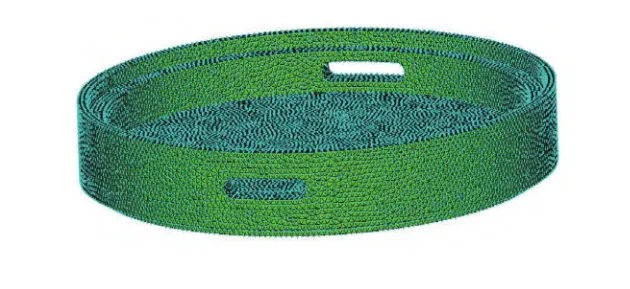
Mesh partitioning is the prerequisite for the whole process of Moldflow analysis, which affects the accuracy of the subsequent optimization. The generated 3D model is imported into Moldflow software because the lens cover parts have relatively thin wall thicknesses and relatively uniform thicknesses. Therefore, it adopts double-level meshing, and the surface mesh is converted into a body mesh. Figure 2 shows the mesh division of the lens cover.
The general requirements of the grid maximum aspect ratio are less than 20, and the average aspect ratio is less than 3. The grid data statistics show that the maximum aspect ratio is 6.88, the minimum aspect ratio is 1.16, and the average aspect ratio is 1.51, in line with the requirements of the mode flow analysis.
Since ABS is selected as the molding material, the process parameters are set as follows: mold surface temperature of 50℃, melt temperature of 230℃, mold opening time of 5s, filling control and injection speed automatically, filling pressure of 80%, and holding time of 10s.
Due to the small size of the lens cap parts, so 1 gate can meet the injection requirements, the gate using a point gate. In the mold flow analysis, three gate position schemes are preset to find the optimal gate position of the part, respectively, in the middle position of the part, the position of the boss, and the position between the boss and the outer circle.
The location between the boss and the outer circle is finally selected using the orthogonal test method, and the corresponding simulation results are analyzed based on this.
1. Gate Position Analysis
1.1 Filling Time
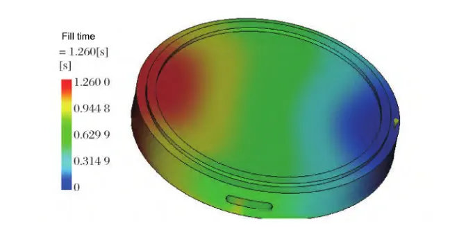
Filling time is the time the plastic takes to melt to fill the whole cavity, which can be used to determine whether there is any hysteresis or short-shot in the molded part. Figure 3 shows the simulation results of the filling time of the lens cap, where the blue color starts filling and the red color fills last.
As can be seen from Fig.3, due to the small overall size of the lens cap, the entire filling process is shorter, only 1.260s, much less than the optimal limit of 5.0s filling time. There is no short shot, cavity-filling uniformity, or mold-filling average.
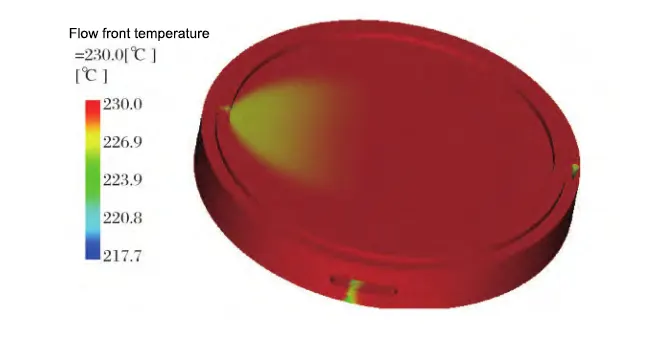
1.2 Flow front temperature
The flow front temperature is the temperature condition of the material melt flowing through the node, a design standard of injection mold. Figure 4 shows the flow front temperature distribution of the molded part. The melt temperature range of the selected ABS material for the lens cover is 200~280℃, and the allowable temperature difference of the flow front temperature is ±20℃, while the flow front temperature range of the molded part is 217.7~230.0℃, and the maximum temperature difference is 12.3℃, which is in full conformity with the standard requirements.
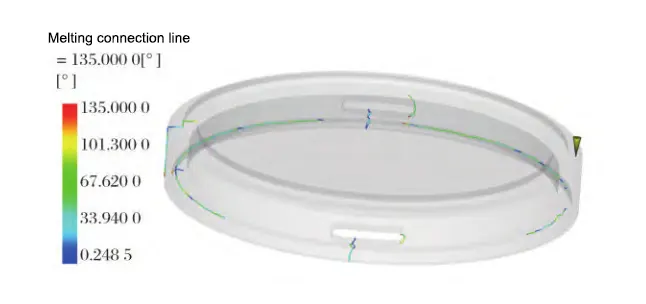
1.3 Fusion marks
When a flow front of the molten material is separated and then combined, welding marks, called fusion marks, will appear. Fusion marks affect the plastic part’s strength and the product’s appearance.
Figure 5 shows the distribution of weld marks on the lens cap. As seen from Figure 5, in the lens cap parts injection molding, the lens cap within the number of welding lines is small and mostly seen in the inside region. This will not directly affect the actual use of the lens cap part’s performance to fully meet the high quality of the lens cap part appearance requirements.
1.4 Air pockets
The injection molding process inevitably produces air pockets. If the air pockets are located in the parting surface, the gas is easily discharged from the gap in the parting surface, greatly improving the appearance of the quality of plastic parts.
Figure 6 shows the distribution of air pockets in the molded part. As can be seen from Figure 6, the molded part in the injection molding process produces fewer air pockets, and most of the air pockets are distributed on the parting surface. The gas can typically be discharged and located in other parts of the minority of the air pockets. The gas can be adjusted utilizing the wall thickness of the part, and molding injection time and other means of eliminating the molding quality are excellent!
The simulation results include comprehensive filling time, flow front temperature, fusion marks, and air pockets. The gate location between the tab and the outer circle can fully meet the actual use of the UAV camera lens cover plastic parts performance and appearance quality requirements.
2. Cooling system design and analysis
In the injection molding process, the cooling system solidifies the melt in the cavity, and the cooling quality directly affects the plastic parts’ performance.
Figure 7 shows the optimized cooling system. After using Moldflow simulation, it was found that the time for plastic parts to reach the ejection temperature without a cooling system was 53.38s. However, Fig.7 shows that the time for plastic parts to reach the ejection temperature after optimizing the default cooling system is 38.38s, reduced by 15s and 28.1%.
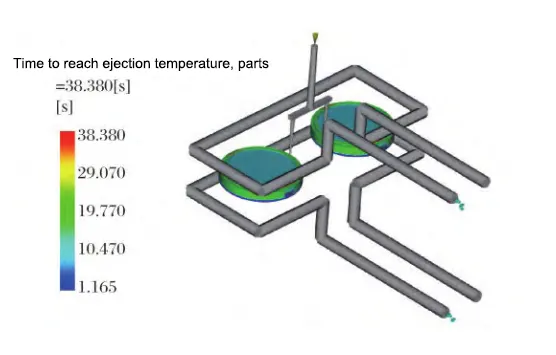
Analysis of the optimized cooling system reveals that the maximum temperature difference of the circuit coolant is 0.45℃, which is in line with the requirement that the temperature difference of the circuit coolant is ≤2℃; the maximum temperature difference of the circuit pipe wall is 5.21℃, which is in line with the requirement that the temperature difference of the circuit pipe wall is ≤5~6℃.
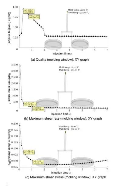
3. Molding window analysis
Molding window analysis can determine the optimal molding process parameters for a product. Figure 8 shows the results of the molding window analysis of the lens cap.
Fig. 8 shows that the lens cap’s molding quality can reach a maximum value of 0.9406 when the mold temperature is 58.0 ℃, the melt temperature is 234.9 ℃, and the injection time is 0.32s. The maximum shear rate is 410s-1, much lower than the material permit of 12,000s-1, and the maximum shear stress is 0.0878MPa, much lower than the material permit of 0.28MPa.
After the molding analysis, the mold temperature of 58.0℃, melt temperature of 234.9℃, and injection time of 0.32s were taken as the optimal molding process parameters for the lens cap of the UAV camera.
4. Bow deformation analysis
Warpage deformation is one of the most common defects in injection molding. If the deformation is too large, it will affect the use and installation of the product, so it is necessary to control the warpage deformation of the molded product.
Set the optimal molding process parameters at the same time, the cooling time is set to 25s, the holding pressure parameter is set to the default, through the “cooling + filling + pressure + warpage analysis” sequence to get the results of warpage deformation analysis of the lens cap in Figure 9.
As seen from Fig.9, the maximum warpage deformation of the plastic part is 0.3119mm. The deformation is small and uniform relative to the whole plastic part. It is within the permissible range and does not affect the product’s assembly.

Selection and checking of injection molding machine
The specification of the injection molding machine is mainly based on the size of the plastic parts to determine, and the processing of plastic parts is primarily through the organic cooperation between the injection molding machine and the injection mold, so the selection of the injection molding machine model is essential.
Based on the mold flow analysis results and careful consideration of the production requirements of the lens cap plastic parts and size parameters, choose the injection molding machine model MA900/260 horizontal injection molding machine, Table 1 for its main technical parameters.
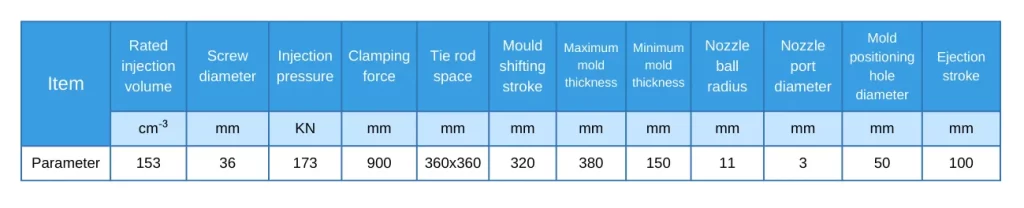
1. Maximum injection capacity checking
When selecting the injection molding machine, the maximum injection capacity is required to be no more than 80% of the rated injection capacity of the injection molding machine, and the injection capacity checking formula is:
Vmax ≤ 80% × V0 (1)
In the formula (1): Vmax is the maximum injection capacity, cm3; V0 is the rated injection capacity of the injection molding machine, cm3.
From the mold flow analysis, the maximum injection capacity Vmax = 17.698cm3 <122.4cm3 to meet the injection capacity requirements.
2. Injection pressure checking
Injection pressure refers to the pressure exerted by the plunger or screw on the unit area of the molten body during injection molding. Its value should be less than the rated injection pressure of the injection molding machine, and the calibration formula for injection pressure is:
P ≤ P0 (2)
Formula (2) in: P for the lens cap molding required injection pressure, MPa; P0 for the rated injection pressure of the injection molding machine, MPa.
From the mold flow analysis, P = 47.2817 MPa <173 MPa to meet the injection pressure requirements.
3. Mold clamping force calibration
To avoid the injection molding of plastic parts due to the role of the injection pressure to make the mold along the parting surface expansion, it is necessary to check the mold clamping force of the injection molding machine. The clamping force of the checking formula is:
F = Pm A ≤ F0 (3)
Formula (3): F for the clamping force, kN; Pm for the average pressure of the plastic melt in the cavity, MPa; A for the molded part and the casting system in the molding surface of the projected area of the sum of the surface, mm 2; F0 for the rated clamping force of the injection molding machine, kN.
From the mold flow analysis, A = 5 141.93 mm 2, Pm = 30 MPa, the clamping force F = 154.257 9 kN <900 kN, in line with the clamping force requirements.
Injection mold design
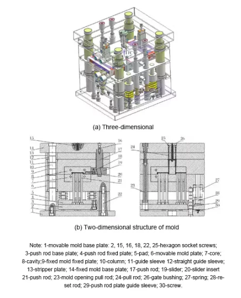
Figure 10 shows the overall structure of the drone camera lens cover injection mold. The working principle is as follows: first, the mold frame is closed, and the injection molding machine injects ABS material into the mold frame. After the material is injected into the cavity, the parts are molded and thoroughly cooled under the cooling system’s action.
In the subsequent demolding stroke, since the mold is designed as a three-plate mold with side core extraction, under the ejection force of the push rod of the injection molding machine, the mold first opens between the 7-core and the 8-cavity, and the cold runner is extracted from the 9-platen while the side core extraction is completed through the 17-toggle lever which pushes the 19-slider;
Next, the mold is opened by pulling the 9-fixed mold fixing plate and the 13-stripper plate through the 23-mold-opening puller, thus completing the pushing out of the cold runner; then the 23-mold-opening puller pulls the 6-dynamic mold plate and the 9-fixed mold fixing plate to open the mold;
Finally, the 21-pusher pushes the product out. Currently, the 27-spring mounted on the 28-reset lever resets the 4-pusher fixing plate and the 3-pusher bottom plate, completing the lens cover injection molding process.
Conclusion
Computer numerical simulation technology is used to carry out a series of moldflow analyses on the gate position, cooling system, molding window, and warpage deformation of the lens cover of the UAV camera. The analysis of the molding window determines the optimal molding parameters of the lens cover part, and the study of warpage deformation completes the validation.
Moldflow software analyzes the whole injection molding process, verifies the simulation results of each value, and finds all the data to meet the design requirements.
Based on the mold flow analysis results, combined with the lens cap’s production requirements and dimensional parameters, the injection molding machine model MA900/260 is selected. The calibration of clamping force, maximum injection capacity, and injection pressure proves that the injection molding chosen machine fully meets the design requirements.
This study completes the injection mold design and principle description of the lens cover of the UAV camera, realizes the full-cycle computer-aided design, shortens the mold design cycle, and reduces the mold design cost.