Reverse engineering in rapid prototyping techniques
Rapid Prototyping technology is a CAD model directly driven by the rapid completion of any complex prototype shape or parts of the advanced manufacturing technology.
RP technology involves CAD technology, data processing technology, numerical control technology, testing and sensing technology, laser technology and other mechanical and electronic technology, materials technology, and computer software technology, which is an organic synthesis of various high-tech technologies and cross-application.
Since the 70s, with the formation of global market integration, the manufacturing industry has been very competitive, and product development speed is increasingly becoming the main contradiction in the competition.
At the same time, the manufacturing industry needs to meet the changing needs of users but also requires manufacturing technology that has strong flexibility and can carry out small batch or even single-piece production without increasing the cost of the product, therefore, the speed of product development and the flexibility of manufacturing technology has become very critical.
Rapid Prototyping technology is generated in this social context, In the late 80’s, RP technology in the United States was first produced and commercialized.
Since then, RP technology has been based on the principle of discrete stacking and features Simply put, the electronic model of the part (e.g., CAD model) way discrete, to become machinable discrete surfaces, discrete lines and discrete points, and then the use of a variety of means, the discrete surfaces, line segments and points stacked to form the overall shape of the part.
Since the process does not require specialized tools, the process planning steps are simple, and, in general, the manufacturing speed is much faster than conventional methods.
For most of the products, it is possible to design their 3D models in common CAD software (Solidworks, Pro/Engineering, etc.) and obtain the corresponding data.
On the other hand, we also need to reproduce or imitate known prototypes or to redesign and improve products.
In some cases, due to the existence of a variety of factors to be taken into account, such as function, process, appearance, etc., the shape of some parts is very complex, and it is difficult to accurately design their solid models in CAD software.
Therefore, it is necessary to first create a small-scale or real-scale physical model of the product, such as wood molds, ceramic molds, etc., and then measure the physical model through the measurements, to obtain the three-dimensional solid model data and process in the computer, which requires the use of reverse engineering.
Basic Concepts of Reverse Engineering
Reverse Engineering (RE) is an emerging discipline, which is of great significance in the rapid design and rapid manufacturing of products.
RE involves a wide range of content, including geometry inversion, material inversion, process inversion, and other aspects.
Among them, geometry inversion has a very important position and role in RE technology, its main task is to construct a CAD model based on the data measured by the physical model, and then use these models and design representations for product analysis and manufacturing.
It can easily and quickly extract data from parts that are difficult to design with CAD as well as from artistic models.
Reverse engineering in rapid prototyping is to measure the physical object in three dimensions by various means, to obtain the data of the prototype, including structure, function, material, etc., and then transfer them to the computer for processing, and use the measurement data to build the three-dimensional CAD model.
With the help of reverse engineering, rapid prototyping technology can be used to quickly replicate the physical object, including enlargement, reduction, modification, etc., and can also be the innovative design of existing products. Rapid prototyping technology itself can also be convenient to make rapid, accurate measurements of the prototype product, used to verify the three-dimensional design and produced or parts and the original design of the degree of conformity, to find out the shortcomings of the product design, re-design, so that the product is more perfect.
It can be seen that the introduction of reverse engineering in rapid prototyping technology can form a closed-loop feedback system including design, manufacturing, and testing of rapid design and manufacturing, which can give full play to the advantages of rapid prototyping and broaden the scope of use of this technology.
Therefore, the general rapid prototyping system has a supporting reverse engineering system.
The application of reverse engineering involves three main aspects.
1) Using reverse engineering to generate STL files for direct use by the data processing software of the RP system to generate NC code; 2) Utilizing reverse engineering to generate STL files for direct use by the data processing software of the RP system to generate NC code.
2) Using reverse technology to generate layer files – CLI files, this output is more suitable for a variety of CT image reverse, and because the RP itself is a layered manufacturing method, tomographic images or vectorized layer contour information directly drive the RP equipment layer by layer superimposed on the three-dimensional entity of the method is also one of the most active areas of research in the academic community.
3) Use the reverse technique to reconstruct the solid model and transform it into STL text with the help of CAD system.
For rapid prototyping technology, the main purpose of the reverse request is to obtain the geometric modeling and structural data of the product.
Through a variety of three-dimensional digitizers to get parts modeling and structural data, with the help of three-dimensional reconstruction technology in CAD software to re-edit (modification and scaling) and then converted into G-code or STL files for rapid prototyping equipment, so that they can be directly processed to produce the corresponding models, molds or parts.
Measurement Methods
Measuring equipment is one of the core hardware in reverse engineering.
There are three main measurement methods used in reverse engineering.
The first is the traditional contact measurement method, such as the coordinate meter measurement method; the second is the non-contact measurement method.
The second is the non-contact measurement method, such as projection grating, laser triangulation, holography, and depth image 3D measurement method.
The third is the layer-by-layer scanning measurement method, such as the industrial method, nuclear magnetic resonance method, and automatic tomography method.
There is also another destructive, and layer-by-layer accumulation of the opposite method, that is, layer-by-layer removal of the measurement method, this method is destructive to the parts, but the data obtained is highly accurate, and in many cases has applications.
These methods have their characteristics and scope of application, the specific choice of measurement methods and data processing techniques, should be based on the measured object’s physical characteristics and application purposes to decide.
At present, there has not been found a fully applicable to rapid prototyping technology, fast, accurate reverse measurement method.
With the development of computer technology and optoelectronic technology in recent years, computer image processing as the main means of non-contact measurement technology, the projection grating method, and the laser triangulation method for rapid prototyping technology is rapidly developing.
These methods of measurement speed, a high degree of automation, suitable for a variety of complex models of three-dimensional rapid measurement tables compare the characteristics of the main three-dimensional scanning methods.
1. Coordinate Measuring Instrument (CMM)
The CMM method, also known as probe scanning, utilizes a CMM contact probe (available in a variety of diameters and shapes) to capture sample surface data point by point.
This is one of the most widely used methods for digitizing 3D models.
When the probe on the probe along the sample surface movement, the sample surface reaction force so that the probe to deform, this deformation is connected to the probe on the three coordinates of the spring generated by the displacement reflected by the size and direction of the sensor measured by the analog converter, the measured signals fed back to the computer through the computer algorithms, display the coordinates of the measured three-dimensional point, and record the data.
Some equipment instrumentation laser beam as a probe to the laser beam focus as a probe for measurement.
The use of CMM can achieve a high degree of measurement accuracy (+ / – 0.5um), the material and color of the object to be measured are generally no special requirements, and the measurement process is relatively simple.
CMM method for no complex internal cavity, feature geometry, only a small number of features curved parts reverse is very effective.
However, because this method is a contact measurement, easy to damage the probe and scratch the surface of the measured sample.
The degree of manual interference, difficult to realize the full automation of measurement; measurement data points are less, can not be directly recovered by the RP method, but also need to modify the model or reconstruct the model in CAD software.
The coordinate measuring machine price is high, the use of the environment also has certain requirements, and the measurement speed is slow.
At present, it is mainly used to measure parts without complex internal cavities, with many feature geometries and only a few feature surfaces.
After obtaining the feature points of the part, the 3D reconstruction is carried out by software, and the solid model is then used for machining.
2. Projection grating method
The basic principle of the projection grating method is to project the grating onto the surface of the measured part, modulated by the height of the measured sample surface, the grating shadow line deformation.
Through the demodulation of the deformed grating shadow line, you can get the measured surface height information, the principle is shown in Figure 1.
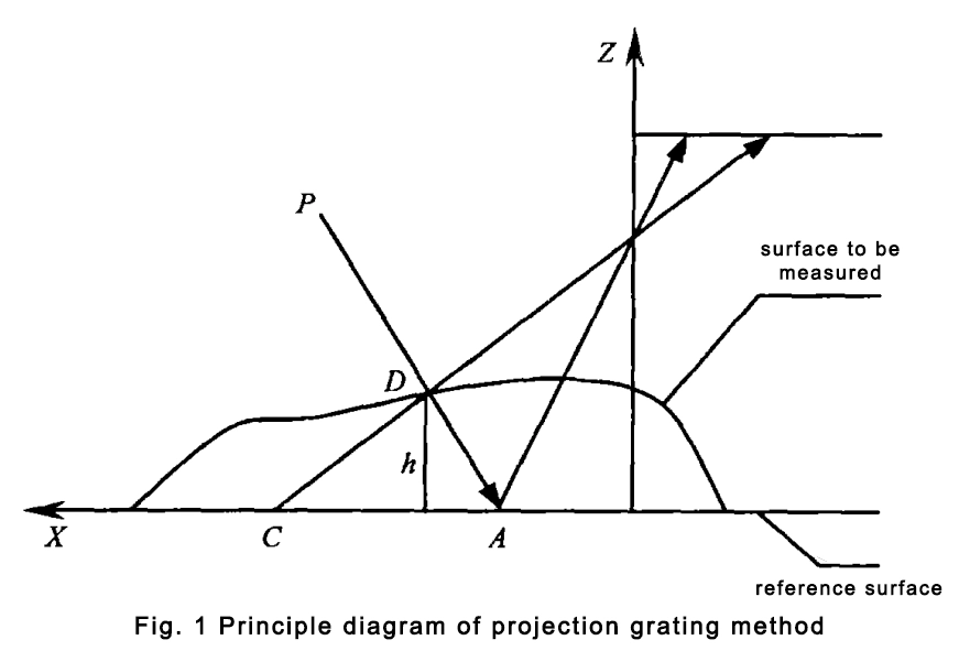
Figure 1 projected grating method principle diagram
People projected light P irradiation to the reference plane on the A point, put on the object under test, and P irradiation to the object under test on the D point, at this time from the direction of the illustration, the A point moved to a new location C point, distance AC carries the height information z = h (x, y), that is, the height of the surface by the shape of the modulation.
Currently, the demodulation of the deformed grating shadow line method is mainly the Fourier analysis and phase shift method.
The Fourier analysis method is easier to automate than the phase shift method, but the accuracy is slightly lower.
The main advantages of the grating method are that the measurement range is large, fast, low cost, and easy to realize. The disadvantage is that the accuracy is low, and can only measure the surface undulation is not too flat object, for the surface changes in the object, in a steep place tends to phase sudden change, so the measurement accuracy is greatly reduced.
3. Laser Triangulation
The basic principle of laser triangulation is the use of a regular geometry of the laser beam (such as point light source, line light source) or analog probe along the surface of the sample continuous scanning of the measured surface, the measured surface of the formation of diffuse reflection of light points (light bands) in the optical path placed on the image sensor (CCD) imaging, according to the principle of triangulation, to measure the spatial coordinates of the point being measured.
The principle is shown in Figure 2, if the height of the target plane is relative to the reference plane for s, then, the two in the detector imaging displacement.
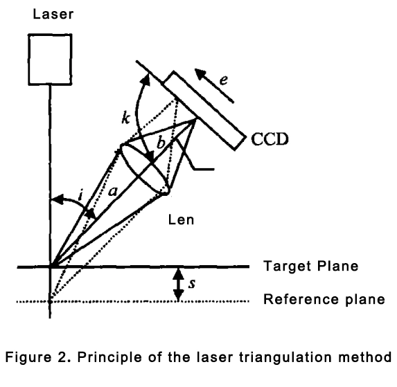
Where a, and b for the lens before and after the focal length, respectively.

Laser triangulation is the most mature and widely used method, it is a fast and accurate measurement.
Laser scanning can not only measure the hard workpiece but also can measure the soft sample.
The main problems of laser triangulation are the surface roughness, diffuse reflectivity, and inclination of the measured surface is too sensitive, there is a “shadow effect”, limiting the scope of use of the probe; can not measure the laser beam can not irradiated position, for the mutation of the step and the deep hole structure is easy to produce data loss; the amount of data obtained by scanning is large, it is necessary to go through the scanning process.
The large amount of data obtained from scanning requires specialized reverse data processing software to build surface models, and the edges and combined parts of the surface need to be repaired manually.
4. CT scanning and MRI
Although the projection grating method and laser triangulation method are widely used, there is a fatal flaw in the application of rapid prototyping technology, i.e., the inability to measure the internal contour of the object, due to the use of the layered superposition method of manufacturing parts, the rapid prototyping process not only needs the external contour data of the sample part but also needs the internal contour data, so the scope of the application of the above methods in the rapid prototyping technology has been greatly restricted.
To solve this problem, a good way is to use CT scanning and MRI technology to directly obtain the cross-section data of the object.
Layer-by-layer scanning is characterized by the ability to accurately measure the surface and internal structure of a part without being limited by the complexity of the object being measured.
The obtained measurement data are dense and complete, and the measurement results include the topology of the part.
However, the accuracy of the data obtained using CT and NMR is low, with the current minimum layer thickness of 1 mm, and it is not possible to make practical mechanical parts with this accuracy.
In addition, the high cost of CT and MRI, coupled with the limited size and material of the parts that can be measured, makes it difficult to use them for rapid prototyping in a short period.
5. Auto-tomography
Auto-tomography is a method of destructive measurement of objects using a combination of layer-by-layer material removal and layer-by-layer optical scanning. It makes the measurement structure greatly simplified, cost reduction, easy to install equipment, and can be sold as a CNC milling machine for removing material accessories.
This method allows automatic and accurate measurement of the surface and internal dimensions of a part and is suitable for rapid prototyping. It has a minimum layer thickness of 0.01mm and a measurement accuracy of +/-0.025mm.
Industrial CT and auto-tomography‘s difference between these two methods is that industrial CT does not destroy the parts and auto-tomography needs to remove the parts layer by layer, although the parts have been damaged (for valuable parts should not be used), but leaves complete data.
In addition, compared with industrial CT, the price is 70 ~ 80% cheaper, but the measurement accuracy is much higher (industrial CT in the Z-axis direction the measurement accuracy is poor, slow measurement speed, expensive equipment, high cost, and automatic tomography scanning in the Z-axis direction of the accuracy of up to 0.025mm), and the realization of a fully automated operation but the method is slower, the general measurement of the part-time is 8 ~ 9H.
Layer-by-layer scanning is the reverse of the RP technique, which uses layer-by-layer summation and is therefore naturally associated with RP. The scanned data itself consists of the contour line data points of a layer-by-layer cross-section of the part, so the measured data does not even have to be converted to an STL file to be processed by RP.
Data Processing
The creation of CAD models from measurement data points is of great importance in reverse engineering. Because the measurement data obtained by various 3D numerical methods are very large (often up to several megabytes, tens of megabytes, or even hundreds of megabytes), and there is usually no corresponding topological relationship between the data, but just a large group of spatial point clouds, including a large amount of useless data.
Therefore, before CAD modeling of measurement data, the data is usually pre-processed, i.e., filtered (removal of impurity points), fitted (approximation and interpolation), reconstructed, and masked.
RP technology requires a slice of the part, and the common data format accepted by RP equipment today is the STL file. There are two ways to obtain STL files.
One is to approximate the CAD model with a large number of triangular slices to form an STL file. The disadvantage of this method is the lengthy conversion process, especially the step of converting the measurement data into a CAD solid or surface model, which is likely to be very difficult and time-consuming, and may not even result in a complete surface or solid model.
Another approach is to generate an STL file directly from the measurement data. Many 3D reconstruction or light modeling software currently use triangular surface algorithms, so it is sufficient to convert these triangular slices into STL file format. This method directly utilizes the measured data points, with less conversion process and high accuracy. The disadvantage is that it is not easy to add support, so it is not suitable for use in SLA, FDM, and other RP processes, and the STL file is too large, if the surface area of the measured part is large and its STL file can reach several hundred megabytes, and may contain a large number of errors, which makes the subsequent processing of the slices bring a lot of difficulties, and even can not be RP processing.
The STL file format itself also has various defects such as redundancy, approximation, and lack of topological information, which makes it difficult to recover the original CAD model from the STL file.
In addition, STEP is an ideal format for data exchange.
It contains geometric, topological, and process information during the product life cycle, is supported by all CAD systems, and can be used in both 3D data formats and slicing formats, avoiding the loss of information and model defects caused by format conversion between CAD and RPM systems, and is expected to become an international standard data exchange format. It is expected to become an international standard data exchange format. This will facilitate the development, application, and promotion of RE and RPM technologies.
Conclusion
Rapid prototyping and reverse engineering are important branches of integrated rapid manufacturing technology that have developed rapidly in recent years.
The combination of the two provides a powerful help for the innovative design of existing products, which can accelerate the speed of product development and greatly improve the ability of enterprises to quickly respond to the market.
Reverse engineering has a significant position in building models based on measurements, scans, photos, or direct measurements of entities.
However, the current level of reverse engineering limits its scope of application.
In the author’s opinion, to match the rapidly developing technology, firstly, it is necessary to further improve the measurement speed, accuracy, and automation of the measurement method, and make it independent of the material of the measured object and the complexity of the internal and external contours; secondly, in terms of data processing, it is necessary to further improve the measurement speed, accuracy and automation of the measurement method.
Secondly, in terms of data processing, should develop a more complete reverse engineering software, that not only can directly deal with the scanning data but also has strong surface modeling and calculation functions, in order to improve the efficiency and quality of the reverse.
Once these problems are solved, the market prospect will be very broad.