Application Cases of Efficient Processing of Injection Molds
Injection molds are widely used in daily production and life such as automobiles, home appliances, 3C, children’s toys, aerospace, etc. The times are developing at a high speed, and the product replacement cycle is getting shorter and shorter, which forces product designers and manufacturers to quickly adapt to the rapid development of the times.
It is difficult for traditional processing methods to adapt to current production needs, so it is necessary to innovate and study efficient CNC processing methods.
This paper has optimized the processing parameters and processing procedures through multiple machine verification and processing comparisons and summarized the efficient processing methods. It provides important reference materials for enterprises at all levels and types to process such molds.
Injection mold analysis
1. Mold core analysis
The mold core consists of holes, inclined surfaces, curved surfaces, and four different bosses. The hexagonal boss composed of seven small cylinders is one of the most difficult points in mold core processing because the distance between adjacent cylindrical bosses is only 2.1mm.
The tool diameter for processing the other three types of bosses is greater than 2.1mm, and the tool cannot enter the processing. Only a tool with a diameter of 2mm can be used for the boundary or for processing a single blank separately, as shown in Figure 1.
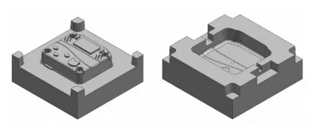
2. Analysis of mold cavity
The mold cavity is mainly composed of grooves, and the bottom of the groove has an R fillet, a V-shaped surface, and a 3° bevel. The difficult-to-process position is the right slider groove.
Research on efficient processing technology solutions
1. Rough processing of mold core
There are 3 roughing methods for mold core processing.
One is the layer-cutting method, which uses the side edge and bottom edge of the milling tool for milling. Generally, the down-cutting step is 0.1~0.2 times the tool diameter, and the line spacing is 0.6~0.8 times the tool diameter. This method is suitable for use when the tool quality is relatively poor, the machine tool is old and the rigidity is poor;
The second is the plunge milling method. The plunge milling method is that the tool mills from the top of the blank to the bottom of the workpiece. This method mainly uses the bottom edge of the tool for milling. It has high requirements for tool quality and high tool consumption;
The third is the Vortex milling method. This processing method mainly uses the side edge of the tool to cut the workpiece. The cutting depth can reach 2 times the tool diameter, and the side edge cutting amount can reach 0.3 times the tool diameter. When cutting at high speed, the processed material flies out like a tornado, hence the name.
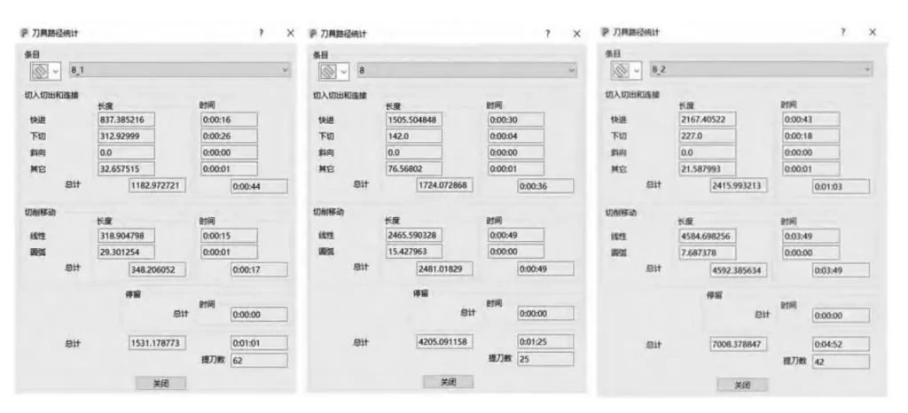
The calculated tool path trajectory uses the contour smoothing function. The tool path trajectory is similar to the racing track line. There is no right-angle turn. It is all arc smooth tool path. There is no machine acceleration-deceleration or machine vibration. The comparison table of important processing parameters is shown in Table 1.
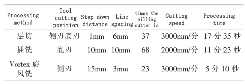
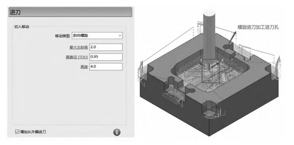
Through the comparative analysis of the data in Table 1, the Vortex milling method is the most efficient processing method for rough machining of this mold core part. The line spacing is 3mm, the down-cutting step is 15mm, the spindle speed is 6000 rpm, the cutting feed rate is 3000mm/min, the down-cutting feed rate is 1800mm/min, the feed method adopts oblique spiral, the maximum left bevel angle is 3°, the circle diameter (TUD) is 0.95, the height is 5mm, and the feed method from the outside is added.
After a statistical processing time of 5 minutes and 10 seconds, the tool is lifted 23 times, as shown in Figure 2.
2. Mold core finishing
After the rough machining of this mold core, only a small amount of machining allowance is left on the side and bottom of the mold. The finishing mainly uses the equal height finishing strategy, parallel flat surface finishing strategy, and 3D offset finishing strategy.
The equal height finishing strategy is used to process the side of the workpiece, the parallel flat surface finishing strategy is used to process the plane position of the workpiece, and the 3D offset finishing strategy is used to process the curved surface of the workpiece.
The mold core side uses the equal height finishing strategy, using a 6mm diameter end mill, a down-cutting step of 0.6mm, a spindle speed of 6000 rpm, a cutting feed rate of 2000mm/min, a down-cutting feed rate of 1200mm/min, and a spiral milling method to process to a flat surface.
If the spiral milling method is not applied, the number of tool lifts will increase. The tool must be lifted once for each milling layer, which will increase the processing time and ultimately affect the processing efficiency.
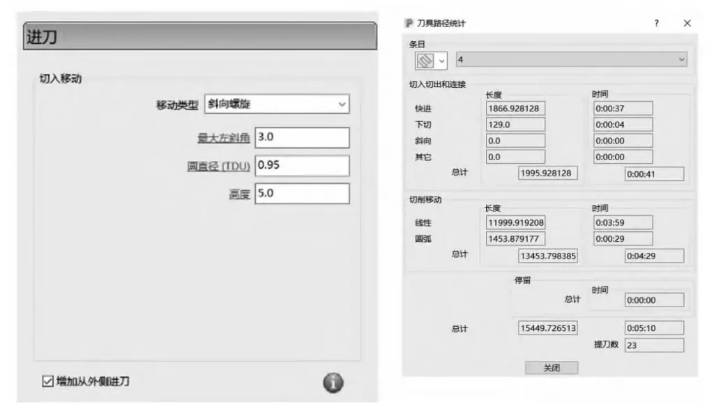
The upper and lower planes of the mold core adopt the parallel flat surface finishing strategy. A 12mm diameter end mill is used to process the large plane with a large line spacing and quickly complete the processing. Then a 4mm diameter end mill is used to process the plane around the boss. The total processing time is 2 minutes and 26 seconds, as shown in Figure 3.
If you are afraid of trouble and do not change the tool and only use a 4mm diameter end mill for processing, the processing time will take 4 minutes and 52 seconds, as shown in Figure 3.
3. Mold cavity rough processing
Mold cavity processing belongs to closed area processing, which is not conducive to chip removal during processing, and the tool cutting position is not good. Compared with mold core processing, the processing environment is poor. Production has time requirements, so efficient processing methods must be studied.
By analyzing the three processing methods of mold core processing, the side milling of the tool is the most ideal and efficient processing method.
The problem is that mold cavity processing is a closed area processing, and how to extend the milling cutter into the bottom of the cavity is the key. Through analysis, there are two methods, one is to use the spiral oblique feed method to first process a feed hole; the other is to use a drill to pre-process a hole before the milling cutter milling.
When the second method is processed, it is necessary to use a drill with a larger diameter than the roughing milling cutter to drill the hole first. According to processing experience, when the drill diameter is greater than 12mm, it is necessary to use a center drill to drill the hole first. In this way, the second method requires two more tool holders and two drills.
For mass production, the second method is applicable because the second method has higher drilling efficiency than milling efficiency and lower tool consumption. The parameters of the efficient processing method of the cavity part are shown in Figure 4 through comparative analysis.
4. Finishing of the mold cavity
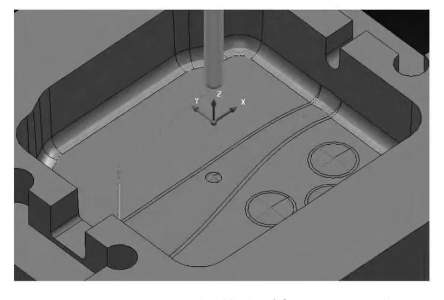
The mold cavity side is finished with an equal height finishing strategy, using a 12mm diameter end mill, 0.6mm step, spiral milling method, spindle speed 6000 rpm, cutting feed rate 3000mm/min, and a total processing time of 2 minutes and 1 second.
The mold cavity bottom is finished with a parallel flat surface finishing strategy, using a 12mm diameter end mill, 8mm line spacing, arbitrary cutting direction, spindle speed 5000 rpm, cutting feed rate 3000mm/min, and a total processing time of 30 seconds.
The most difficult feature in mold cavity processing is the fillet R3 at the bottom of the cavity. How to make the fillet R3 smooth and have a good surface roughness? The surface roughness level of the mold cavity directly affects the outer surface quality of the injection molded product.
There are two processing methods for rounded corners, one is the processing tool path in the radial direction perpendicular to the R angle, and the other is the processing tool path in the radial direction parallel to the R angle.
To meet the surface quality of the final product, the processing tool path in the radial direction perpendicular to the R angle is used to process this cavity part. The processing tool path is shown in Figure 5.
Post-processing
After the tool path optimization is determined, the tool path trajectory (tool location source file) needs to be converted into NC program code that can be read by the corresponding CNC system three-axis or multi-axis machining machine through a dedicated post-processor.
The instruction code and program format of different CNC systems are quite different, and the post-processor needs to be modified accordingly.
The key to the development of CNC machine tool post-processors is to set the travel limits of the moving axis and the rotating axis, otherwise, processing accidents will occur during program operation, damaging the workpiece or machine tool.
After the tool path simulation shows that there are no problems such as tool interference, select all the machining tool paths, call the developed post-processor program, enter the file name of the generated NC program, and you can generate the NC code program used for CNC machine tool processing.
Application of efficient machining process solutions
1. Selection of important parameters of the machining center
The machine model used for this machining is CY-VMC1060 vertical machining center, equipped with FANUC 0i MD CNC system, spindle maximum speed 6000r/min, fastest feed speed 6000mm/min, repeat positioning accuracy 0.02mm, machine weight 7000KG, X/Y/Z travel 1000mm/600mm/600mm respectively, tool magazine capacity 20 tool cup positions, external DNC.
2. Important parameters of tool installation
After multiple program optimization and modifications, simulation verification, and comparative analysis on the machine, the efficient machining process solution for the core and cavity parts was finally determined.
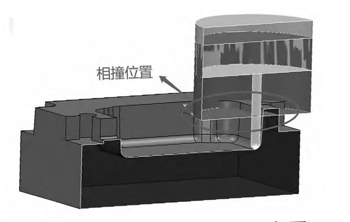
Since this involves mold cavity processing, the length of the tool extending from the shank must be considered when clamping the tool. If this detail is not paid attention to, there will be a collision between the shank and the workpiece (as shown in Figure 6), resulting in damage to the shank and the workpiece, thus affecting the processing efficiency.
To avoid tool collision accidents, the length of the tool extending from the shank must be considered clearly when installing the tool, and the diameter specifications of the shank and blade must also be considered.
For example, the D4R2 ball head milling cutter used this time, the conventional milling cutter of this model has a shank diameter of 6mm, and the effective cutting edge is 4mm and is only about 10mm long.
If the depth of the mold cavity is greater than 10mm, it cannot be processed. To complete the processing in quality and quantity, a D4R2 ball head milling cutter with a shank diameter of 4mm must be customized.
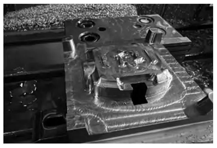
3. Workpiece clamping method
The mold core and mold cavity are regular parts, and a universal fixture precision vise is used for clamping. The processing process is shown in Figure 7.
Conclusion
Through the practical application research on efficient processing of injection molds, the processing efficiency is effectively improved by more than 30%. Taking production practice as an example, the comparison and analysis of roughing parameter settings, the comparison and analysis of fine processing parameter settings, and the demonstration of important tool installation parameters are verified, and finally, the efficient processing method of injection molds is obtained, which further verifies the advantages of this efficient processing method.