From challenge to advantage: Undercut solutions in injection molding
Some undercut features are inevitable
In the injection molding process, it’s important to avoid designs that have undercut features, as they can cause problems when removing the product from the mold. But sometimes, these undercuts are necessary for the product to work properly. So, product designers need to learn undercut molding methods. By understanding this, designers will know what’s possible, what’s not, and how it affects the cost of making the mold and injection molding. This article will explain different ways to create these undercuts in molds.
The ways to deal with undercut injection molding include adjusting the parting line, incorporating slots, using core pulls, slider mechanisms, lifters, sacrificial cores, bump-offs, hand-loaded cores, unscrewing mechanisms, and collapsible cores. More information on each of these methods will be provided below.
Adjusting Parting Line
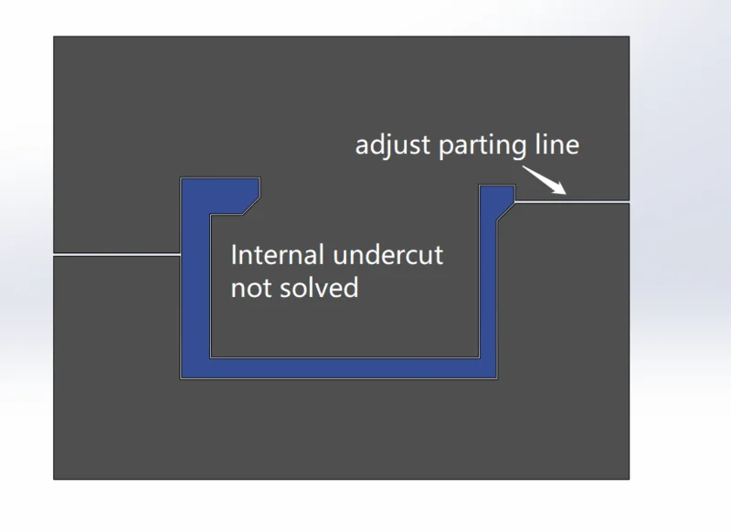
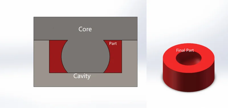
A parting line for a mold in injection molding is the boundary or dividing line between the two halves of a mold, known as the “core” and the “cavity.” This line marks the separation point where these mold halves meet and separate to release the finished molded product. Move the mold’s parting line to the point where the undercut begins, and in doing so, the undercut will cease to be an undercut. This method is only suitable for undercuts on the outside of the part. It cannot address undercuts within the part. Adjusting the parting line hardly increases mold manufacturing costs. This method should be applied whenever possible.
Incorporating slots
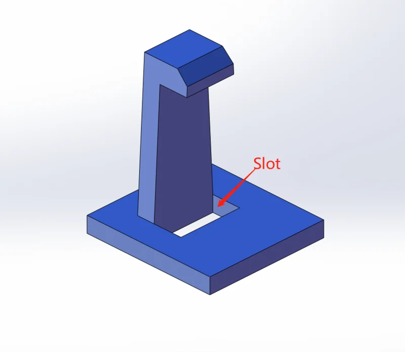
Creating a groove at the bottom of the undercut and removing the obstructing plastic can also solve the undercut problem. This method also hardly increases the mold production cost, but the groove may impact the part’s appearance, strength, and sometimes its functionality. It is not suitable for all situations.
Core Pulls
As shown in Figure 1, the lower side of the part forms an undercut. The side cores are driven by a pneumatic or hydraulic mechanism. This mechanism is connected to the hydraulic or pneumatic pressure of the injection molding machine during the injection molding process. Either before opening the mold or before the part is ejected, the core is pulled, and then the part is ejected.
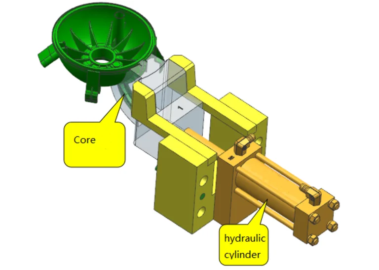
For longer core travel or when greater force is needed, hydraulic core retraction is employed. When rapid injection molding is required and the travel distance is small, a pneumatic drive is often used. This core pull structure requires some extra parts to support the core retraction mechanism but still is a relatively simple mold design approach. Compared to other structures, it is relatively uncomplicated, and it doesn’t significantly increase the mold manufacturing cost. The additional cost of cylinders, whether hydraulic or pneumatic, is also reasonable.
However, during the production process, it’s important to be vigilant about potential oil or air leaks.
Lifter Mechanisms & Slider Mechanisms
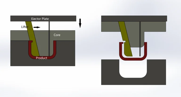
Lifter mechanisms are typically designed as movable elements within the mold. When the mold opens, in the ejection process, these mechanisms move in a vertical direction, lifting the molded part away from the undercut features, thus allowing it to be safely ejected from the mold. This movement helps to release the part from the mold without causing damage or deformation. Lifters are usually used to address internal undercuts.
Sliders work by moving horizontally within the mold. When the mold opens, these sliders move parallel to the mold’s parting line, allowing the molded part to be released smoothly from the undercut areas. By sliding in and out, they create the necessary clearance for the part to be ejected without getting stuck or damaged in the process. Sliders are usually used to address external undercuts.
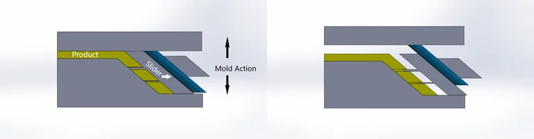
Both lifters and sliders involve complex mold structures, they increase the mold manufacturing cost a lot. However, these mechanisms are considered to be the most reliable method for undercut injection molding. Hence are very popular in mold design.
Bump-offs
Bump-offs involve creating a movable feature or component in the mold that can push or “bump off” the molded part from an undercut during the ejection process. This allows for the successful removal of the part from the mold, even when undercuts are present, ensuring a smooth and efficient plastic injection molding process.
When using bump-offs in the mold design for plastic injection molding, the plastic product may experience a slight deformation or flexing as the mold opens. The bump-off mechanism is designed to apply controlled force to release the molded part, especially if there are complex undercuts. This controlled force can cause some temporary deformation or flexing in the plastic product. However, the plastic typically regains its intended shape once it is fully released from the mold due to its elastic properties. The degree of deformation and the material’s ability to flex back depends on various factors such as the material properties, design, and the specific bump-off mechanism used in the mold.
Bump-offs should be used for rather flexible materials, hard and brittle material could break. And the ‘bump-off’ angle should be 30~45 degrees. Fiber-reinforced material is generally not suited for bump-offs, fiber glass or fiber carbon makes plastic brittle and easy to break with bump-offs.
Bump-off designs are relatively cheap compared with the lifter or the slider solution, but the usage is limited by material and injection molded parts’ complexity.
Hand-loaded Cores
The hand-loaded core is an alternative method of a lifter or slider. Instead of lifting or sliding the interlocking features of the core, it’s turned into a removable part or an insert. After the product is ejected, the insert is removed manually. Since the insert has to be manually put into the injection mold and removed after injection, this method increases the labor cost and injection molding cycling time. It does save mold cost compared with lifter or slider design. Not all undercuts can be solved in this way. For small-volume production or complex undercuts, this method is a good solution.
Unscrewing Mechanisms
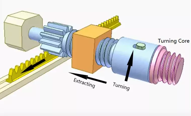
Screw threads in an injection molded part create undercuts. To address this, a turning core is needed. The turning action is either powered by mold opening action or a hydraulic cylinder.
When opening the mold, before the opening action, the hydraulic cylinder drives through a series of gears, rotates, unscrews, and extracts the turning core. So that the screw thread is not stripped by the mold opening action.
The unscrewing mechanism is specifically designed to address the screw thread undercut features. It requires an extra 3 or more gears and a couple of bearings in the mechanism. Operators have to be very careful with mold maintenance and make sure the gears are not damaged or misaligned. Both the maintenance and extra mechanisms increase the mold cost. But it is still the most common method to address the screw thread undercut problems.
Collapsible Cores
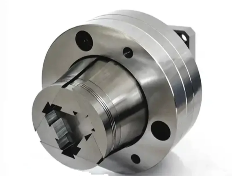
Collapsible cores are specialized components used in plastic injection molding to handle undercuts or complex part geometries. They are designed to create internal features or cavities within a plastic part that would typically prevent easy ejection from the mold.
Here’s how they work:
Initial Shape: Initially, the collapsible core is in a larger shape that fits into the mold, allowing the injection of plastic around it.
Injection: Plastic material is injected into the mold around the collapsible core, taking the shape of the mold and the collapsible core’s initial form.
Retraction: After the plastic material cools and solidifies, the collapsible core is retracted or collapsed inward. This creates the internal undercut features or cavities in the molded part.
Ejection: Once the collapsible core is retracted, the molded part with the internal features is easily ejected from the mold.
Collapsible cores are particularly useful for creating complex parts with internal undercuts, threads, holes, or other intricate features that would otherwise be challenging to manufacture using conventional molding techniques. They allow for efficient production of complex parts while ensuring smooth ejection from the mold.
Collapsible cores involve intricate structures made from highly precise metal components, contributing significantly to additional mold expenses. As a result, they are most effectively utilized in scenarios of high-volume production or in instances where alternative mold designs struggle to accommodate the demands of injection molding for a particular part.
Talk with experts when you have doubts
In conclusion, navigating the intricate landscape of undercuts in injection molding is indeed a challenging journey. However, with the right expertise and resources, like those offered at CapableMachining, what seems like a challenge can effortlessly transform into a strategic advantage. Our team of experts is dedicated to providing tailored solutions that not only address undercuts effectively but elevate the entire injection molding process. Discover how we turn challenges into opportunities, paving the way for seamless production and exceptional results. Reach out to us today and let’s embark on this journey of transformation together.
As a trusted supplier in the plastic industry, Elitepipe Plastic Factory has established long-term partnerships with clients who value their high-quality products and reliable performance. Elitepipe Plastic Factory
Let’s be.
I join. I agree with told all above. We can communicate on this theme. Here or in PM.