How does the 5-axis CNC perform machining?
Five-axis linkage CNC machining technology did not appear before parts processing. A three-axis machine tool was used in the past. The machine tool can meet most types of parts processing manufacturing, but its efficiency is low, its quality is relatively poor, and it is difficult to complete the manufacture of some complex parts.
In this context, the machining field gradually developed a higher efficiency and quality of parts processing technology, that is, five-axis CNC machining technology, after much research.
However, it should be noted that because the technology uses a rotary axis, which will lead to sudden changes in the axis vector, in the high-speed machining process, it is easy to damage the tool or workpiece, so the application of this technology is still not very widespread.
Overview of the part model
1. Part size
This paper selected the S-shaped test piece as the object of study for the five-axis linkage CNC machining technology research.
An S-shaped test piece is one of the common tools in modern machinery manufacturing. Through the application of an S-shaped test piece, the machine tool can be inspected to determine whether there are defects in it, avoiding the production of parts that do not meet the specifications’ requirements.
S-shaped test specimen is a more complex structure of the part, composed of two parts, one for the S-shaped edge of the bar, the thickness of its regions are identical, the other is a rectangular base for the edge of the bar’s support, in the upper part of the base, contains 4 step holes, for workpiece clamping;
The upper part of the base has 4 stepped holes for workpiece clamping and 2 positioning holes for mounting, positioning, and measuring reference. Its structural parameters are shown in Fig. 1.
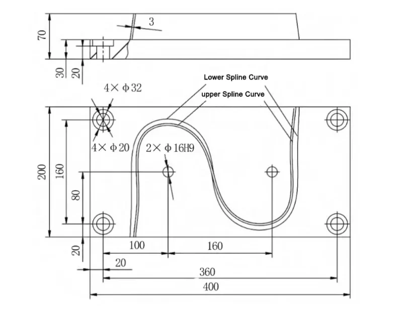
When machining the S-shaped specimen, the upper surface of the base is the Z=0mm plane, and the positioning hole φ16H9 on the left side of the rectangular datum is used as the center to construct the corresponding coordinate system.
The height of the rectangular base is 30mm, and a step hole is reserved at the four corners.
Install the S-shaped edge strip, which is 3mm thick, on top of the base. There is a certain angle between the base and the strip, and the two are not perpendicular.
2. Modeling process
Due to the complex structure of the S-shaped specimen, its modeling process is more cumbersome. Specifically, after logging into the corresponding modeling software, enter two groups of data points, each group of 50, for a total of 100, one group in the Z = 0mm plane and one group in the Z = 40mm plane.
Based on this, the corresponding three-section spline curve is constructed in each plane, and then the curve is used as a guideline to construct a straight-line surface by straight-line sweeping.
The straight surface is then stretched by 3mm in the X-axis direction to increase its thickness to 3mm, thus obtaining the upper edge strip.
Finally, in the new page of the software, the base model is drawn, and six holes are constructed in the appropriate position of the model by Boolean difference. Four are used as stepped holes, and two are used as positioning holes to complete the modeling work of the whole S-shaped specimen.
CNC Programming
1. Machining process analysis
Through the analysis of the S-shaped test piece model, it can be found that there is a certain angle between the edge and the base. The two are not perpendicular, belonging to the non-straight wall parts, so they are difficult to process with three-axis machine tools.
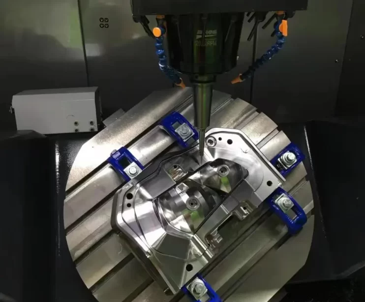
This study adopts five-axis linkage CNC machining technology for S-type specimen processing. First, it builds the S-type specimen processing process card. Then, it utilizes the CAM system containing the UG NX function to design the corresponding machining toolpath trajectory.
The pre-command is generated through multi-axis milling. Next, the AB double pendulum head type five-axis post-processor is constructed. Finally, the S-type specimen is CNC machined under the pre-command’s control.
Under the control of the pre-instruction, we can get the G code for the CNC machining of the S-type test piece.
When machining an S-type specimen, the best machining method must be chosen, and reasonable cutting parameters must be set according to the specimen’s material characteristics.
For the specimen used in this study, 7175-T7451 aluminum alloy is selected, and its rim is 3mm thick, which is typical of thin-walled parts.
In addition, there is a certain angle between the rim and the base, which is a non-straight-walled part.
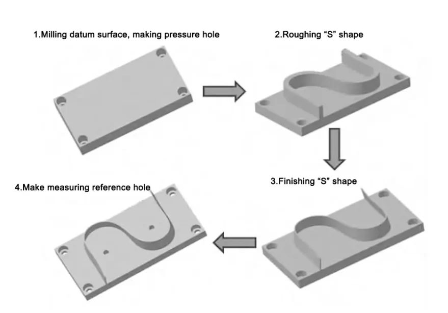
The machining process card can be obtained according to the specimen’s material and structural characteristics. It mainly contains four links, respectively, for rough machining of blanks, edge rough machining, edge finishing, and reference hole machining, as shown in Figure 2.
2. Toolpath Planning
According to the test piece machining process, we can determine the machining content of each link, design the machining method of each link, and select the best machining tool, as shown in Table 1.
Table 1 Machining content and tool selection
For the programming steps of UG CAM, first in the software, the pre-built model opens, and it jumps to the UG machining programming interface.
Then, based on this, combined with the machining process, load the blank and set the corresponding parameters.
2.1 Countersunk Hole Processing
The processing of countersunk holes is mainly completed by Process 1 and Process 2.
In the corresponding dialog box of the interface, input “drill”, which can automatically jump to the drilling interface.
In this interface, three tool models are constructed, respectively:
(1) Tool T1 is a Spotdrilling-Tool center drill with a radius of 10mm and a length of 65mm, which is used as a processing tool for locating holes;
(2) Tool T2, a Drilling-Tool, with a radius of 10mm and a length of 65mm, is used as a tool for φ20 through-hole processing;
(3) Tool T3 is a counterboring tool with a radius of 16mm and a length of 50mm, which is used as a processing tool for φ32 countersunk holes.
After that, the design process begins: choose the center hole, then the through hole, and finally the countersunk hole to end the machining process of the link.
2.2 Cavity milling
Mainly completed by process 3, the operation procedure is as follows:
In the cavity milling interface, construct an end mill model with a radius of 16mm and a corner radius of 3mm.
Then, set the parameters of the part, blank, and so on.
Design the tool trajectory according to the structural characteristics of the part and set the cutting method, i.e., “follow the periphery”;
Add cutting parameters, of which, for the bottom surface allowance, set to 0.5mm, for the side wall allowance, set to 2mm;
Add the feed rate parameter, set the running speed, and click OK to automatically get the tool track control.
2.3 S-face finish machining
This link is the focus of the entire S-shaped specimen processing, directly related to the processing quality of the entire specimen.
Various finishing methods can be used for the structural characteristics of S-shaped specimens, the following four being common.
(1) Sequential milling.
Click the “Create” option, in the column of multi-axis milling, click “Sequential milling”, and then jump to the corresponding programming interface.
In this interface, build a model of an end mill with a radius of 10mm;
Construct the safety plane;
In the “Feed Setting” item, determine the feed mode, set the corresponding reference point, and select the matching geometry;
In the “Toolpath movement” item, construct the check, drive surfaces, and the surfaces of the parts;
Finish pushing the tool.
(2) Profile milling.
In the column of multi-axis milling, click “contour milling” to jump to the corresponding programming interface.
In this interface, build the milling cutter model and construct the geometry according to the first method.
After that, use the upper surface of the base as the bottom surface and the edge surface as the sidewall.
In the “Drive method” item, select “Profile milling”;
In the item “Tool axis setting”, select the automatic mode;
In the “Machining Method” item, click the Finishing option.
(3) Layered contour milling.
Based on the second method, select each of the eight auxiliary surfaces and further process the edge strip by layering.
(4) Layered variable contour milling.
In the Multi-Axis Milling column, click on “Variable Contour Milling”;
Treat the surface of the edge strip as a driving surface, and in the “Cutting Mode” item, select Single Phase and set the Step Distance to 6;
In the Projection Vector item, click Facing Driver;
In the “Tool Axis Mode” item, click Side Edge Driver;
Other operations and settings are the same as the first method.
2.4 Machining of the base surface and center hole
It is mainly completed by Process 5 and Process 6, which is used to measure the machining accuracy of the whole specimen.
Enter the interface of process creation, in the column of “Drilling Mode”, click “Standard Drilling” to jump to the interface of hole processing; construct a drill to the model with a radius of 8mm;
Set the reference hole;
Set the safety distance valley value to 80mm;
In the “Cycle Type” item, select “Standard Drill”.
3. 5-axis post-processing
Recognizing the toolpath data is usually tricky for CNC machine tools, and applying it directly to S-shaped test piece machining is impossible.
At the same time, the internal structure of different machine tools is different, and the connected CNC systems are not the same.
Therefore, after obtaining the tool position trajectory data, it should be processed appropriately so that it can be changed into the corresponding program representation recognized by the CNC machine tool. This process is post-processing.
This study uses a dedicated post-processing element in which UG/Post Builer is used as a development tool.
The parameters for the machine’s type and characteristics are set in the post-processing element.
On this basis, the toolpath data is transferred to the post-processing element and automatically transformed into the corresponding post commands.
Virtual machining simulation
1. Construction of the simulation platform
The VERICUT system is used for CNC simulation software.
The system constructs the corresponding machine tool model topology based on the machine tool’s operating characteristics and the setting of the relevant parameters.
In the UG interface, the three-dimensional model of each machine tool is drawn.
Based on this, each block is continuously exported. Then, in view of the characteristics of the topological structure, it is transferred to the VERICUT system, and the relevant parameters of the components are set to obtain the model of the AB Double Pendulum 5-axis Linkage CNC machine tool.
After obtaining the machine model, the position and motion mode should be initialized to keep the machine model in the initial state.
Finally, the corresponding control system is recorded in the model to be used for automation control during part machining. In this study, 840D CNC software was chosen.
2. NC Post-program Verification
In the “Project Tree” column, select “Coordinate System” to build a new coordinate system; in the coordinate system, click “Stock (0,0,0)”, select a 400×200×40mm rectangular block, and obtain the blank model. In the coordinate system, click “Stock (0,0,0)” and select a 400×200×40mm rectangular block to get the blank model;
Click “Design (0,0,0)” to import the model of the test piece;
Right-click on the “machining tool”, select “Tool Manager”, and then click “Add” -> “Tool” -> “New” -> “Milling” to build 6 tools;
Click on “Program” to load the converted post instruction;
In the “Item above” column, click on “Position: 1”, select “G-code” to jump to the “Radial tool compensation” list, and set up the “Radial tool compensation” list, and set up the “Radial tool compensation” list. Select “G-code” to jump to the “Radial tool compensation” list and set the corresponding parameters;
Select “G-code offset” to set the coordinate system.
After that, click “Save” and select “Start.” The machine will automatically complete the S-shaped specimen machining operation.
3. Model Error Comparison
When machining the S-shaped specimen in this way, there is no problem of over-cutting or under-cutting, and there is no collision during the whole machining process, which shows that the machining technology has a better application effect.
This paper also introduced the above four ways into the simulation software and decomposed the specimen simulation processing analysis to further understand the accuracy of different S-shaped surface finishing methods.
Through the observation of the four analytical models, it can be found that when the first method is used, a large number of round boxes with a large area appear within the surface of the S-shaped specimen, indicating a large error; when the second method is used, a large area of circular madness also occurs, indicating that the error is also high.
When the latter two methods were used, the area of the rounded boxes was tiny, especially in the third method, where the area of the rounded boxes was negligible. Thus, the third method had the highest machining accuracy.
Cutting test
According to the above process, the third S-face finishing method is the main one, and 7075-T7451 aluminum alloy is used to make the S-shaped test piece.
On the edge of the test piece, three intercept lines are set at 10mm, 22.5mm, and 30mm, respectively, and 25 inspection points are set at the same spacing.
Then, based on this, the normal error of each point is deduced by comparing it with the theoretical model.
Finally, the standard error structure is projected onto the surface of the S-shaped specimen utilizing visualization technology, and different gray values are used to differentiate the error situation; the brighter the surface is, the higher the value of positive error that exists, and vice versa, the higher the value of negative error is.
The test results can be observed. For the five-axis linkage CNC machining technology introduced in this paper, the reverse error is small, in the range of ±50μm, in line with the specified requirements.
Conclusion
In summary, five-axis linkage CNC machining technology is a relatively common method of parts processing in modern machining. The use of this technology can not only quickly complete the processing of complex parts but also improve the accuracy of parts processing. The error is controlled within the range of ±50μm, in line with the specified requirements, and therefore can be promoted to the processing of complex parts.