How to analyze and optimize the mold flow of injection molded parts?
A set of high-quality injection molds is inseparable from reasonable design and exquisite processing. Traditional mold design mainly relies on the experience of designers. After the mold is designed and processed, it often needs to be repeatedly debugged and modified before it can be officially put into production. The efficiency is too low, can no longer be used, and can even meet production needs. Even experienced engineers can take weeks or even months to design a new mold, and accuracy is difficult to guarantee.
With the continuous improvement of professional software, the utilization of injection mold flow analysis technology can analyze the rationality of mold design in advance, reduce the number of mold trials, accelerate product development, and consequently enhance enterprise efficiency. While the use of high-end CAD/CAE/CAM design software for manufacturing can significantly boost mold design efficiency and shorten manufacturing time, it solely approaches issues from a design perspective and may not adequately address certain challenges in actual injection molding production.
Moldflow is professional software utilized for designing and manufacturing plastic products and molds. It can simulate the entire injection molding process and its impact on injection-molded products, evaluate and optimize the entire process, and analyze plastics prior to mold manufacturing. This optimization spans product design, production, and quality, offering a comprehensive solution for enhancing enterprise product design and manufacturing. It assists technicians in optimizing various key points throughout the entire process.
So how does it work? Let’s take a practical example to illustrate how it can provide designers with efficient negotiated solutions.
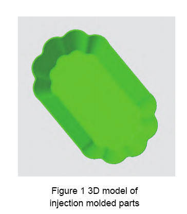
As depicted in Figure 1, the injection molded part is a small plate. If the mold design is flawed, the material selection is inappropriate, or the process parameters during injection molding are not properly set, the resulting injection molded parts may exhibit quality defects such as warping deformation, flash, weld marks, and prolonged molding cycles.
To enhance mold development efficiency, reduce the development cycle, minimize the number of mold trials, and improve the product qualification rate, Moldflow software is employed to conduct mold flow analysis on the injection molding process of these parts prior to mold development. Initially, the optimal gate position is determined and filled with injection molded parts.
Subsequently, molding analysis calculations including filling analysis, holding pressure analysis, and warpage analysis are utilized to predict potential quality issues of the injection molded parts.
Finally, by analyzing optimization plans, the best materials for injection molded parts are selected to enhance product quality, production efficiency, and the qualification rate of injection molded parts while concurrently improving efficiency, shortening the product development cycle, and reducing mold development costs.
Mold flow analysis of injection molded parts
1. Model modeling and pre-processing
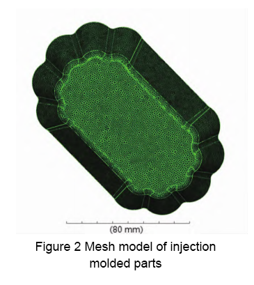
The three-dimensional model of the injection molded part is shown in Figure 1. The overall dimensions are 140 mm × 85 mm × 3 mm, and the wall thickness is 1.5 mm. A 3D solid mesh model is used to divide the finite element mesh, and the global mesh side length is 1.3 mm. A CAD mesh model of the small plate was created, with a total of 822,409 mesh units. The mesh model was diagnosed and repaired, with an average aspect ratio of 7.38, as shown in Figure 2.
2. Analysis of optimal gate location
The positioning of the gate directly impacts the flow of the melt within the mold cavity, consequently influencing the orientation of polymer molecules and post-molding product warpage. Thus, selecting a suitable gate position is paramount in mold product design.
In the mold design stage, Moldflow’s powerful analysis capabilities can be utilized to comprehensively assess flow resistance and balance, determining the optimal gate position to ensure flow equilibrium. This enables rational mold system and gate position design, mitigating potential issues and enhancing the success rate of initial mold trials. Consequently, it shortens the product design and launch cycle, significantly reduces production costs, and bolsters corporate competitiveness.
The findings of the gate position analysis serve as vital considerations for setting the gate position. This setting should comprehensively account for factors such as melt flow, appearance quality of injection molded products, mechanical properties of molded products, and mold design and manufacturing. Moldflow’s gate position analysis module aids in identifying a preliminary optimal gate position for the design analysis process, providing valuable reference points for design decisions.
Select “Gate Position” for mold flow analysis.
Select the default material PE for injection molded parts, the manufacturer is Dow Chemical Europe, and the grade is KS 10100 UE. Just select the default value for the process settings and perform analysis and calculation.
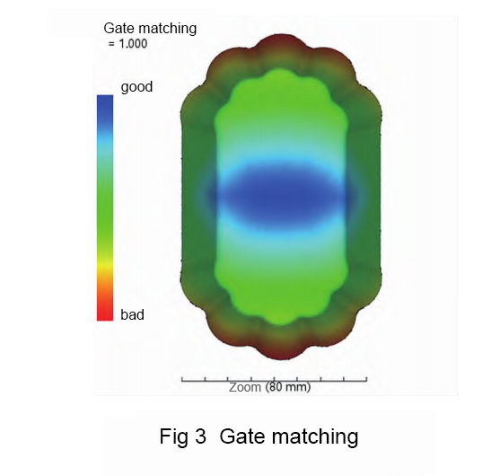
The gate position analysis results are shown in Figure 3, including gate matching and flow resistance indicators. It can be seen that the bottom center position of the injection molded part is the optimal gate position.
According to the gate position analysis results, the bottom center node of the injection molded part is used as the inlet gate, as shown in Figure 4.

3. Analysis sequence and molding process settings
The analysis sequence can be selected according to needs: filling, filling + holding pressure, fast filling, filling + holding pressure + warpage, cooling, cooling + filling + holding pressure + warping, molding window, gate position, cooling (FEM), and cooling (FEM) + filling + packing + warpage and other analysis types.
In this case, the injection molding process selection system has default settings. The process parameters include mold surface temperature, melt temperature, injection pressure, holding pressure, holding time, cooling time, etc.
The mold flow analysis type of injection molded parts selects filling + holding + warpage to analyze the melt flow behavior during small plate injection molding, the impact of the holding stage on the quality of injection molded parts, as well as the amount of warpage deformation and influencing factors. The process parameters can be directly selected from the default values recommended by the system.
The small plate model preprocessing and analysis parameter settings are completed. Select Analysis to start analysis and calculation.
4. Analysis of mold flow analysis results
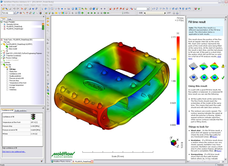
The mold flow analysis results of injection molded parts are shown in Figure 5. The filling time of the small plate is 0.8694s, the flow front temperature is 227~232.7 ℃, the pressure during speed and pressure switching is 44.26 MPa, and the volume shrinkage rate is large at 30.84 s. is 19.68%, the average volume shrinkage is 3.103%~18%, but the warpage deformation is too large, reaching 1.43 mm, and the warpage deformation is as high as 10.21%; the injection welding line is located at the last filling position, at the edge of the injection molded part, and will not adversely affects the quality and appearance of injection molded parts. Similarly, the gas cavity is also located at the edge of the injection molded part, that is, at the parting line. The parting line can be used for exhaust and has basically no impact on the injection molded part.
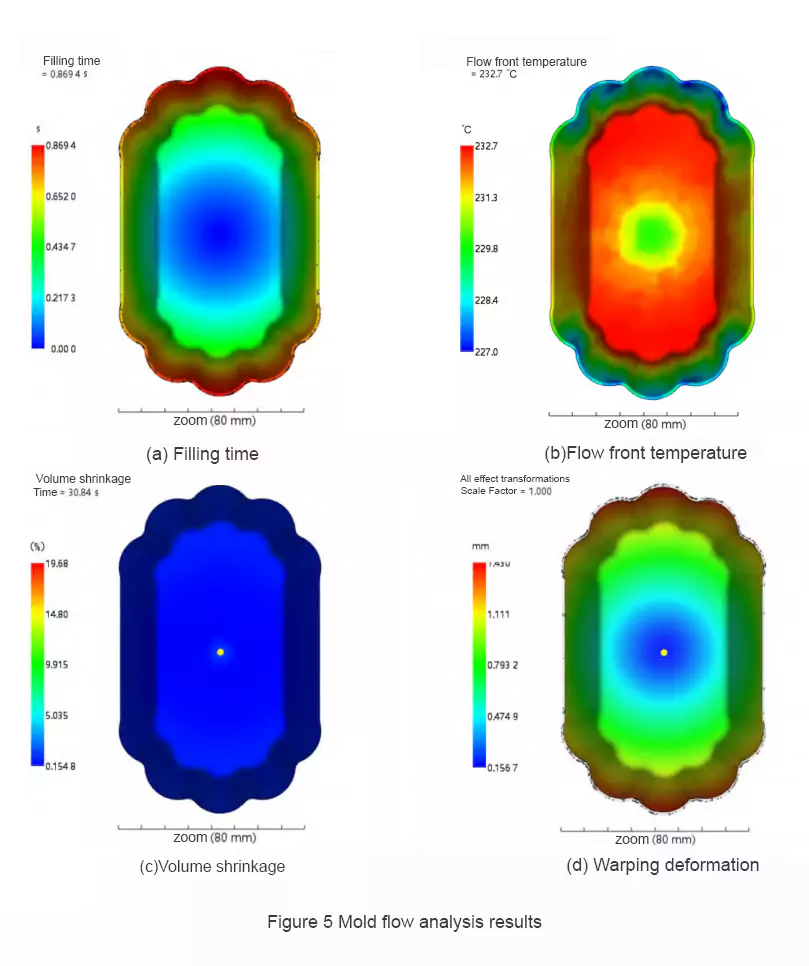
Through the analysis above, the primary issue with injection molded parts is identified as a significant volume shrinkage rate, resulting in severe warpage deformation. Therefore, to optimize the quality of injection molded parts, efforts must focus on reducing the volume shrinkage rate and controlling it in all directions. This approach aims to minimize warpage deformation of the injection molded parts.
Optimization analysis of injection molded parts
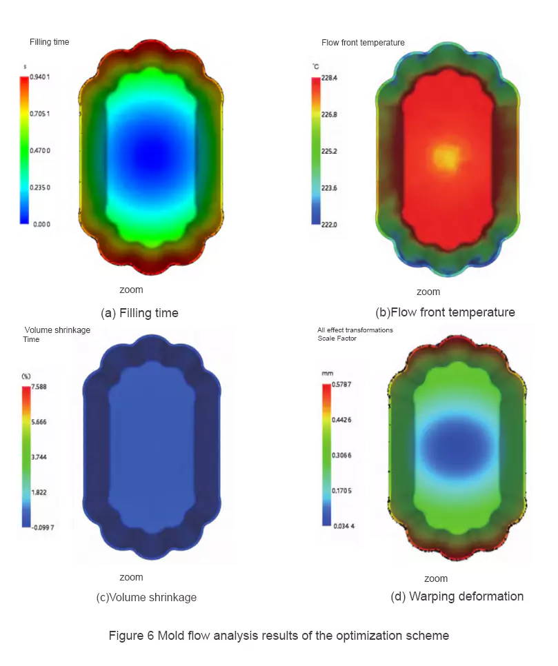
Based on the results of mold flow analysis of injection molded parts, the excessive warpage deformation is attributed to the large volume shrinkage rate. To enhance product quality without altering the product structure, this reduction can be attained by material substitution. A decrease in volume shrinkage mitigates warpage deformation resulting from inconsistent volume shrinkage in all directions. For instance, opting for PS material from manufacturer INEOS Styrolution, branded as Styrolution PS 1300, illustrates this approach. Moldflow optimization analysis yields the results depicted in Figure 6.
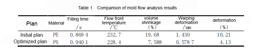
According to the mold flow analysis results of the optimized solution, the volume shrinkage of the injection molded parts was reduced from 19.68% to 7.588%, the average volume shrinkage was reduced from 18% to 6.173%, and the total warpage deformation was reduced from 1.43 mm to 0.578 7 mm, the warpage deformation is reduced from 10.21% to 4.13%. The optimization effect is quite obvious, see Table 1.
Conclusion
Utilizing Moldflow mold flow analysis technology aids in the design of newly developed injection molded parts by predicting potential quality issues in the mold design scheme and conducting optimized design and analysis.
The results demonstrate that employing Moldflow mold flow analysis technology can effectively reduce warpage deformation in injection molded parts, decreasing it from 1.43 mm to 0.578 7 mm, and lowering warpage deformation from 10.21% to 4.13%. This offers valuable insights for the development of injection molded parts, thereby averting potential errors that may arise solely from empirical evaluation and avoiding increased costs associated with repeated mold trials and repairs.
This significantly contributes to reducing development costs and cycles while substantially enhancing product molding quality.