How to choice milling cutter?
Modern machining cutting processes work not only to improve the maximum processing quality but also to produce repeatable action accuracy so that the operator carefully and cautiously correctly selects the right cutting tool.
However, when it comes to difficult to process and for some challenging and difficult to process materials, after processing the use of parts in the harsh conditions of the environment, the choice of tools be careful and important and shorten the processing time, high-efficiency parts processing.
Milling cutter diameter selection
The blade machining process’s steps and selection of tool conditions are very complex. Here, the choice of high-speed tool path familiar software, CAD / CAM system, processing in the high-speed linear oscillating tool path in the precise control of the tool contact surface of the eat knife arc length, so as to obtain a very high cutting speed and accuracy.
When the milling cutter cuts into instantaneous angles or other complex geometries, the cutter feed does not increase even though the angle changes.
Technicians have invented advanced diameter small milling cutters to take better advantage of this technological advancement by designing and researching cutter makers.
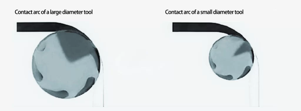
Small-diameter milling cutters can also be used with high-speed toolpaths to effectively remove more workpiece stock in the same time and environment, obtaining higher metal removal efficiencies while reducing labor for the machinist. Figure 1 compares the contact surfaces during machining between a large-diameter milling cutter and a small-diameter milling cutter, as shown in Figure 1.


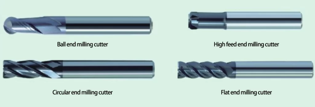
Fig. 2 Several milling cutter types suitable for machining hard metal materials. During machining, the tool’s cutting edge is in frequent contact with the surface of the workpiece, which is particularly likely to lead to rapid tool life failure.
An empirical method is introduced: choose a milling cutter with a diameter 1/2 the size of the narrowest part of the workpiece.
At this time, the radius of the selected milling cutter must be smaller than the size of the narrowest part of the workpiece, the cutting part of the tool will have the location of the left and right to move and space, and can obtain the smallest eating angle. The milling cutter the machinist selects can be used with multiple cutting edges and higher feed rates.
In addition, there is the advantage that when using a milling cutter with a diameter of 1/2 the size of the narrowest part of the workpiece, it is possible to maintain a small draft angle of the milling cutter during machining. The angle does not increase when the tool is rotated in the cutter’s direction, so the original draft angle is continuously maintained.
As an added benefit, the stiffness of the machine tool also helps determine the size of the cutter that can be used.
For example, when cutting on a machine with a taper of 40, the machinist can choose a milling cutter diameter that should normally be <12.7mm.
Violation of this law, if the processor uses a cutting tool diameter milling cutter, it is likely to produce more than the machine’s ability to withstand a large cutting force, resulting in the processing of workpiece vibration, deformation, the surface finish becomes very poor and accelerates the life of the tool to wear, workpiece machining results can not meet the requirements of the dimensional accuracy.
If the processor adopts this new high-speed tool path, the milling cutter in the cutting processed workpiece corners issued by the cutting sound and straight line cutting are the same.
The milling cutter issued the same sound during the cutting process, indicating that the machining process is not subject to localized large thermal and mechanical shocks.
Suppose the cutting edge of the milling cutter makes a sharp, harsh sound every time it turns a corner or cuts into a narrow part of the workpiece. In that case, this indicates that the diameter of the cutter may need to be reduced to minimize the draft angle.
Suppose the cutting edge of the milling cutter in each steering movement, cut into the workpiece’s narrow corner, and cut other parts of the sound, is identical. In that case, the status quo shows that the milling cutter to withstand a uniform cutting pressure did not change with the geometry of the workpiece and fluctuations up and down, this is because of the draft angle is always kept constant.
Milling of narrow parts
Milling narrow parts can choose a large feed milling cutter suitable for narrow parts of the milling process, each time the principle of thinning the cutting allowance, choose a higher feed rate for milling, the same can be completed processing requirements.
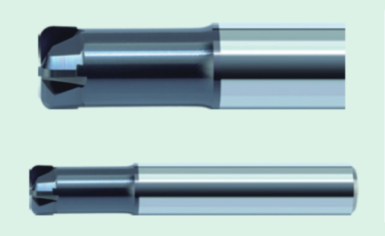
In the spiral milling holes and milling ribs during processing, the cutting edge of the tool frequently has friction with the processing surface. The use of large feed milling cutter milling can minimize the contact with the surface of the workpiece, thereby reducing the cutting heat as well as good control of the deformation of the tool in the process of machining, such as in Figure 3.

Figure 3 Large feed milling cutter suitable for machining narrow parts of these two processing, the first large feed milling cutter cutting under normal circumstances in a semi-closed state. Therefore, processing found that the maximum radial travel distance should be about 25% of the diameter of the milling cutter, and each time, the maximum Z-axis depth of cut into the workpiece for each travel should be 2% ~ 3% of the diameter of the milling cutter.
In the spiral milling process, when the milling cutter to spiral cutter trajectory is cut into the workpiece, the spiral angle of the incision is greater than 2 degrees less than 4 degrees until it reaches 2% of the diameter of the milling cutter Z depth of cut.
The second is the choice of processing tools for extensive feed milling cutter cutting in the open state; then, the radial travel distance will depend on the hardness of the workpiece material. For example, when milling workpiece materials with a hardness of HRC30-50, the maximum radial travel should be 5% of the milling cutter diameter;
If the hardness of the workpiece is higher than HRC50, the maximum radial travel and the maximum Z-axis depth of cut for each pass are 2% of the cutter diameter.
Milling straight walls
When milling straight walls with flat ribs or straight walls, the best results are obtained with circular cutters with 4 and 6 flutes, which are particularly suitable for milling with straight walls or very open areas for profiling.
The greater the number of cutting edges of the selected milling cutter, the greater the feed rate that can be used. However, it should be noted that the machining programmer must minimize the number of times the tool comes into contact with the surface of the workpiece while using a smaller radial depth of cut width.
Do not rule out that some machine tools are less rigid, in such a machine tool, or choose a smaller diameter milling cutter is more conducive to processing, small diameter milling cutter can reduce the surface contact with the workpiece.
Attention to the place, multi-flute arc milling cutter step, and depth of cut with a large feed milling cutter are the same. Grooving can be performed on hardened materials using a pendulum toolpath.
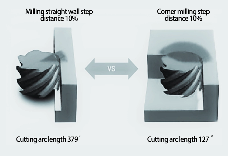
Selection of the grooving milling cutter, the processor should choose the diameter of the milling cutter, about 50% of the width of the groove, to ensure that the milling cutter has a large enough space to move to ensure that the milling cutter machining will not increase the angle of the cutter to eat as well as to reduce the machining of too much heat of the cutting. Figure 4 compares milling a straight wall and a side wall.

Conclusion
The proper selection of a tool for particular complex machining depends on the machining material and the type of cutting and milling method used.
By preparing well before machining, thinking about the machining process in advance, and optimizing tools, cutting speeds, feed rates, and machining programming techniques, the machinist will be able to produce parts faster and better with lower machining costs.