How to deal with overcutting and undercutting in CNC machine tool processing?
CNC machine tools have become an essential development in the field of machining. They are widely used in modern machining because they offer a high degree of automation, high processing accuracy, and strong adaptability to parts.
However, CNC machine tools in the processing of the problem can not be as easily adjusted manually as ordinary machine tools can be; therefore, in the CNC machining, one must pay attention to every detail of the machining process, carefully consider, and strive to be accurate.
In the actual programming, improper trajectory processing, process irrationality, and other reasons often lead to excessive cutting or undercutting, i.e., overcutting or undercutting. Overcutting will directly affect the accuracy of parts processing and even lead to the processing of product scrap. Therefore, it must attract sufficient attention.
Select feed rate is not appropriate, resulting in overcutting or undercutting.
In contour machining, when the part’s contour has a corner, the tool easily produces an “overtravel” phenomenon.
As shown in Figure 1, the milling cutter from A to B movement, when the feed rate is higher, due to inertia, in the corner of the metal may appear overcutting phenomenon, that is, the corner of the metal more cut to some.
If the surface is convex outward, B will have part of the metal is not removed, that is, the phenomenon of undercutting, so that the contour surface error.
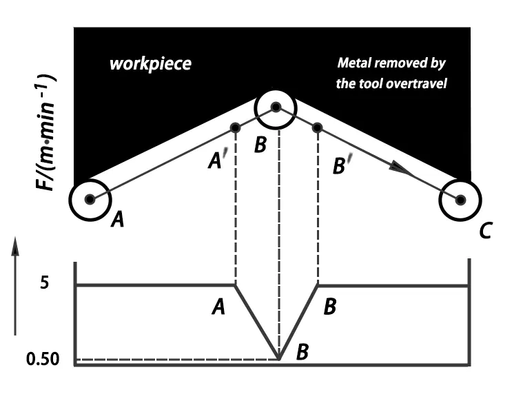
In the programming, the solution is to close to the corner before the appropriate reduction in feed rate, after the corner, and then gradually increase the speed. AB is divided into two sections: the AA′ section uses the standard feed rate to the A ′ to start decelerating after B ′ and then gradually return to the standard feed rate, thereby reducing the amount of overtravel.
At present, some perfect automatic programming systems have an over-travel verification function. Once the detection of an over-travel error exceeds the permissible value, it can be set up to control the appropriate “deceleration” or “pause” program section.
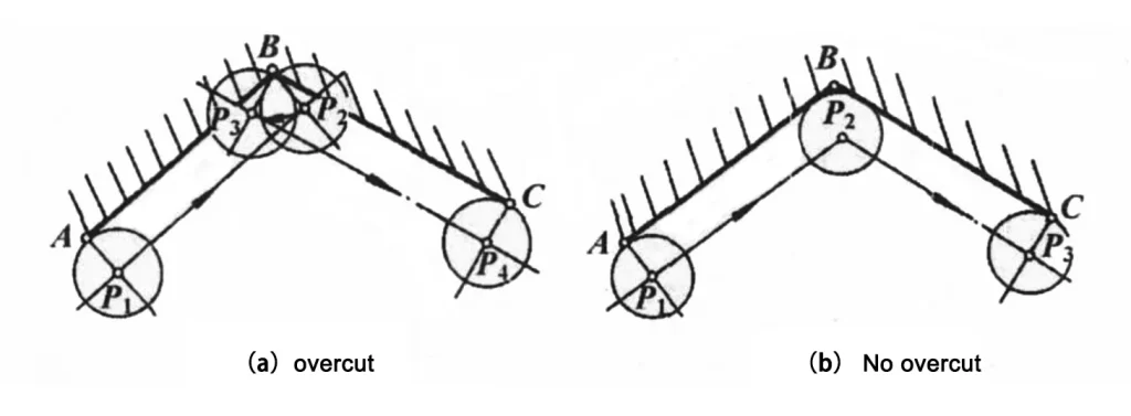
Figure 2 shows the tool’s proper compensation machining inner contour surface. Programming trajectory for the A-BC, there are two kinds of tool center trajectory, Figure 2 (a) according to the theoretical tool center trajectory to move P1-P2 -P3 -P4, will produce the phenomenon of overcutting, damage to the workpiece;
Figure 2 (b) shows the computer processing after the knife center trajectory, with no overcutting, knife center trajectory P1 -P2 -P3.
Using Transition Arcs at Sharp Corners to Prevent Overcutting
Sometimes, due to the use of folding lines to approximate the curve did not notice (or unexpected) the sharp corners of the convex or concave, especially in the vicinity of the curve inflection point is not easy to distinguish, this time, such as the use of transition arc programming at the sharp corners will be straightforward to produce the phenomenon of overcutting, as shown in Figure 3 (a).
Sometimes, because of the convex shape near the sharp corner of the contour restrictions, such as milling cutter diameter is too large, the sharp corner of the transition arc programming will also produce overcutting, as shown in Figure 3 (b).
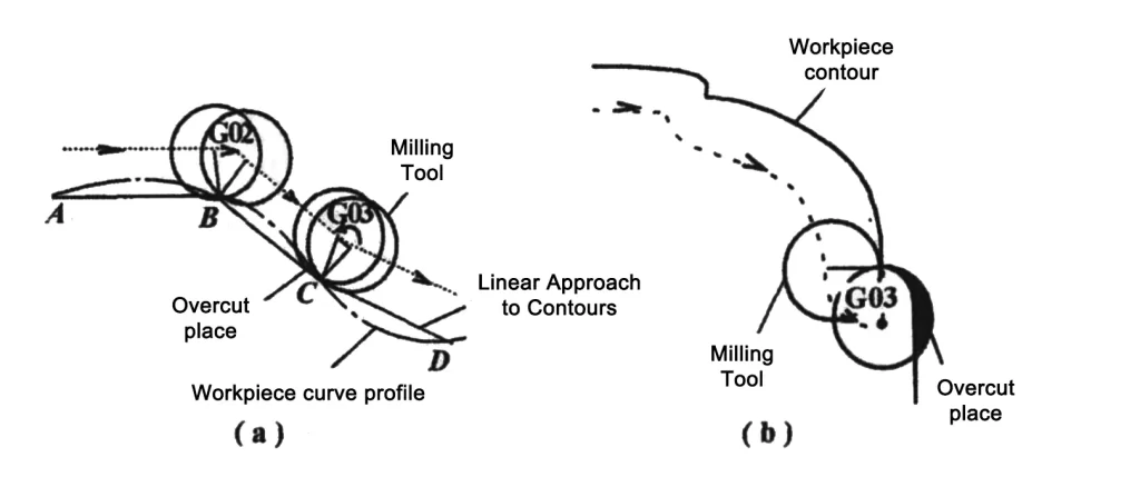
When encountering the above situation, the solution is to give up the sharp corners of the transition arc programming.
Angle transition processing
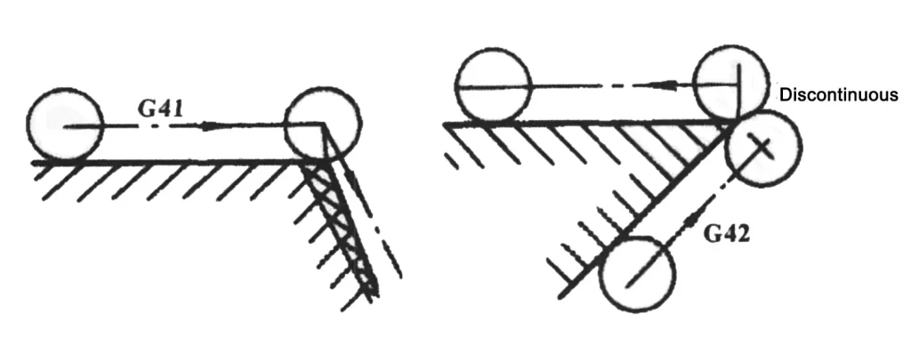
CNC milling machine milling angular contour, if the center of the tool displacement and contour size is the same, there may be overcutting phenomenon or the center of the tool trajectory can not be continuous phenomenon, as shown in Figure 4. For this reason, in the preparation of the workpiece processing program, should consider the transition trajectory of the corner, reasonable arrangements for the transition program.
Solution. As shown in Figure 5, it is a standard method of angular transition processing.
Figure 5 (a) in the corner is formed by a straight line and a straight contour line of the corner. The program’s preparation and the tool’s center must be extended to the center track.
To the transition point S, as seen in the figure, the transition point should be the intersection of the two tool center trajectories;
A straight line and arc profile curve angles form figure 5 (b). Write the program, the center of the tool movement must extend to the transition point S, and then along the straight line SA to write a section of straight-line machining program, and then write the arc machining program;
Figure 5 (c) is a round arc and straight line contour line formed by the prism, the machining program, add three straight line program;
Figure 5 (d) shows the inner contour tool center trajectory. The above method can be used to handle other angular transition processing methods.
Improper instruction will cause overcutting or the undercutting phenomenon.
1. When machining beveled surfaces, improper tool position offset instructions will produce overcutting or an undercutting phenomenon.
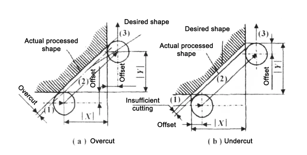
The situation shown in Fig. 6 (a) is due to the overcutting phenomenon caused by the improper use of tool position offset instruction, and the inappropriate programming program is as follows:
…
N1 G01 XF Moves horizontally to the right;
N2 G45 XYD Move along the diagonal line, extending the offset by 1x;
N3 Y moves vertically upward;
…
As shown in Figure 6 (b), due to the use of tool position offset instruction improperly caused by the phenomenon of undercutting, the improper programming program is as follows:
…
N1 G01 G45 X F D Move horizontally to the right, extending the offset by 1x;
N2 X Y Move along the diagonal;
N3 G45 Y Move vertically upward, extending the offset by 1x;
…
The solution is to avoid tool position offset commands when machining slanted surfaces.
2. After the automatic tool compensation has been established, it is impossible to insert two or more program segments consecutively that have nothing to do with the coordinates of the movement in the plane of the tool compensation; otherwise, overcutting will occur.
In the use of G40, G41, G42 instructions to establish the automatic tool compensation function, it should be noted that: when continuous use (two or more) does not contain interpolation plane coordinates of the program segments, should not contain interpolation plane coordinates of the previous program segments should be added to indicate the direction of the following tool movement of the coordinates of the indication (I, J, K in any two), otherwise it will cause overcutting.
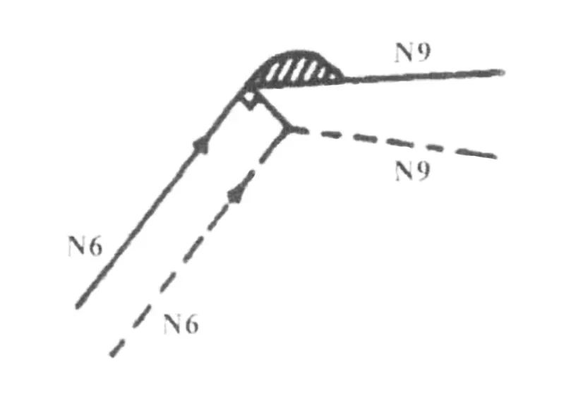
For example, the following program segments N7 and N8 do not contain the coordinates of the interpolation plane, which executes the phenomenon of overcutting, as shown in Figure 7.
N6 G91 G42 D07 X10000 Y20000
N7 S21 T05 M08
N8 G04 X1000
N9 X10000
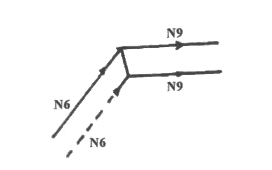
The solution is to change to the following form:
n6 g91 g42 d07 x10000 y20000 i10000 j0
N7 S21 T05 M08
N8 G04 X1000
N9 X10000
can avoid overcutting, then its cutting trajectory is shown in Figure 8.
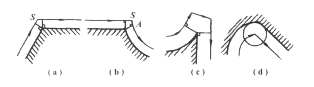
Establishment or withdrawal of the path of the tool patch improperly caused by overcutting
In the tool into and out of the workpiece, should pay attention to the route into and out of the tool, to prevent interference between the tool and the workpiece overcutting or undercutting, as shown in Figure 9, the use of tool radius left compensation G41 or proper compensation G42, when the tool is close to the contour of the workpiece, the numerical control device is considered to be from the center of the tool coordinates change to the tool and the contour of the outer circle of the tangent point of the coordinate value, if from the direction of the tool shown in Figure 9 (a) will interfere, change to Figure 9 (b) to avoid overcutting.
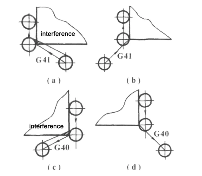
When the tool is away from the contour of the workpiece, the CNC device is considered to be the coordinates of the point of tangency between the tool and the contour from the tool center coordinates, if the direction shown in Figure 9 (c) back from the tool will be interfered with, change to the direction shown in Figure 9 (d) back to avoid overcutting.
If the processing data start and end points are not closed, feed and retreat tool positions will not coordinate, resulting in undercutting.
The key to solving undercutting is to close the curve data over the actual entry point curve and then back off, eliminating tool marks.
Conclusion analysis
The above analysis of CNC milling and undercutting, which includes several possible occurrences and corresponding measures, focuses on studying the reasons for overcutting and corresponding measures.
In CNC machine tool processing, a reasonable process analysis, the correct preparation of machining programs, and machining to meet the requirements of the parts have specific and practical significance.
Of course, there may be some other reasons for overcutting, such as fixture rigidity, the machine itself, round-trip clearance and other impacts, in practice, we must analyze and deal with specific machine tools for specific.