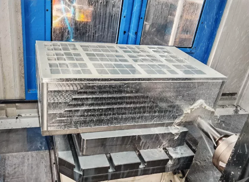
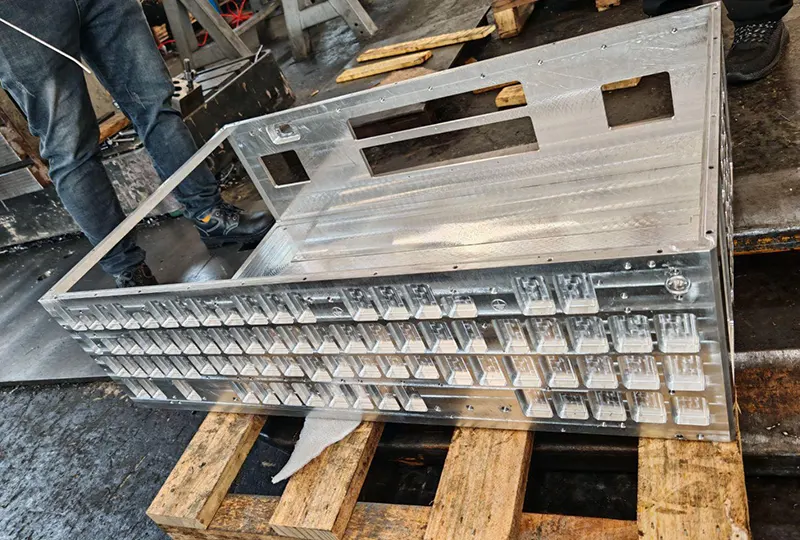
How to do the process and its fixture design for box parts machining?
Box parts have higher requirements for size specifications and positional accuracy, making the machining process more complicated.
Processing should accurately determine the benchmark, make a reasonable choice of machining process methods, and use a scientific combination of machining processes to improve the qualification rate of box parts machining products, ensure the quality and efficiency of box parts machining, and effectively control the processing cost.
Processing should also be reasonable to determine the type of production and blank processing methods, a sensible choice of positioning benchmarks, a scientific combination of machining processes, accurate calculation of machining allowances, and other process parameters, to ensure the box parts’ machining accuracy.
Fixture quality and performance impact box parts machining efficiency and accuracy, so they should be combined with the actual requirements of the box parts design fixture.
The design of fixtures should strictly comply with the relevant design specifications and technical standards, according to the design points to reasonably determine the relevant parameters, and constantly optimize the design scheme so that the design of fixtures is more practical.
Box parts machining process
Box parts on the machining process requirements are high. This paper presents an inclusive support drive mechanism in the box parts processing as an example, and the machining process is analyzed for the box parts machining fixture design.
Box parts production type
Box parts machining should be based on the planned output, production schedule and other calculations to analyze the average scrap rate and spare parts rate, to determine the type of box parts production reasonably. In this paper, the box parts are produced using small batch processing.
Box parts blank processing mode
Blank casting processes and small batch processing generally choose pressure casting, metal molding, die forging, and other processing techniques.
Combined with the yield and accuracy requirements, the box parts machining metal mold casting process can improve the internal structure of the box parts and unit area of the organization of the density of the yield, in addition to a reasonable choice of blank material type.
Select workpiece positioning reference
According to the machining accuracy requirements, the positioning datum includes coarse and fine datums. Box parts machining, with a reasonable choice of positioning reference, is an important part of the machining process.
In initial processing, the blank surface is usually the workpiece positioning reference. Determining the rough datum is the first process of box parts machining.
When selecting the coarse datum, the unprocessed surface of the blank should be chosen. The surface should be necessary but not reused. At the same time, the surface should be easy to clamp and control machining allowances.
When selecting the fine datum, it should ensure that the benchmark coincides with the unity, not only to be able to sense the benchmark but also for each other as a benchmark, to effectively control the value of the positioning error and improve the box parts of the product qualification rate.
Box parts machining process
In-box parts machining is more involved in the processing technology and process links, so the processing practice should combine scientific processes to improve processing efficiency and reduce processing costs.
According to the characteristics of the box parts machining production type, the process route is shortened by the principle of process concentration of process combinations to ensure the machining accuracy of the parts.
Box parts machining techniques
Box parts machining should be based on parts processing size, geometry, and machining accuracy requirements to select and optimize the process route.
This paper mainly covers the processing of box parts, which includes blank casting, aging treatment, scribing, rough milling, rough turning, drilling, reaming, rough reaming, boring, tapping, deburring, and cleaning.
Determine the process route, which should be based on the machining accuracy requirements, positioning benchmarks, whether easy to clamp, whether the fixture can be reused, the number of required machine tools, and whether the process of machining needs to change the machine tool, and so on, to determine a reasonable process route.
At the same time, it should also consider the way the parts are processed, the parts scrap rate, etc. to optimize the process route further, reduce the number of clamping and machine tool changes, and improve productivity and processing quality.
Box parts machining allowance
Machining allowance refers to the thickness of the metal layer on the surface of the workpiece cut off during machining, and the reasonable determination of the machining allowance has an essential impact on the machining accuracy of the box parts.
Therefore, according to the relevant technical specifications, the machining allowance of each machining process should be calculated to analyze and accurately determine the process parameters to ensure the processing quality of the parts and reduce processing costs.
Box parts processing machine tools
Box parts processing should be based on the size of the outer contour of the parts, the processing accuracy, and the selection of machine tools for the production type. Drilling, boring, and other machining processes need to use specialized machine tools, while tapping, milling, chamfering, and other machining processes generally use general-purpose machine tools.
Production units should be based on the box parts machining process requirements to choose the type of machine tool.
Box parts machining fixture
Cutting processing requires the use of fixtures for workpiece positioning, so a reasonable choice of fixtures is conducive to the performance of the machine tool process and improves machining accuracy and efficiency.
There are some differences in box parts machining between various types of fixtures, different fixtures of the application range, and different power sources. General-purpose fixtures are mainly applicable to small quantities or single-part processing.
Specialized fixtures are mainly suitable for processing more than a batch of parts. Production practice should be based on the type of production and machining accuracy requirements, such as the choice of fixtures.
Box parts machining tools
Different processing techniques, workpiece size specifications, and machining accuracy of different tool requirements. Box parts machining should be based on the requirements of the process manual to select the appropriate standard tool.
Box parts machine fixture design
Box parts machining lathe fixture design
Lathe fixtures are essential auxiliary tools for parts, such as end faces and rotating surface machining. Lathe fixture design to ensure that the axis of rotation of the machine tool spindle and the centerline of the workpiece are consistent.
Design principles
When designing lathe fixtures for box parts machining, the structural form of the positioning device should be scientifically selected. Attention should be paid to the rationality of the layout position, and the design should be based on the fixture’s rotary axis to locate the component benchmark.
The design of the clamping device should include a comprehensive analysis of the cutting torque, centrifugal force, gravity, etc., to ensure that the clamping force of the clamping mechanism and self-locking performance meet the requirements of box parts machining.
Fixture design using angle iron type should fully consider the drag force mode. Designers should fully understand the characteristics of the machining process and the benchmark to determine how to improve the feasibility of the design program.
When designing the positioning elements of a lathe fixture, the structural form and layout of the positioning elements should be determined according to the axial coincidence requirements to ensure that the machining accuracy of the parts meets the process requirements.
When the lathe fixture design adopts the disc type or angle iron type structure, pay attention to the fixture balance, which can take the configuration of a counterweight block and other ways to reduce the vibration caused by an asymmetric fixture structure.
The fixture structure layout should be compact, and the center of gravity and spindle should be similar. If conditions allow, the cantilever should be as short as possible to shorten its size.
The design should also be based on the fixture contour line to determine the size of the components to avoid components beyond the fixture contour; this can be set on the fixture shield and other devices to avoid coolant or cutting splash damage to the fixture.
Design points
The rough machining process of the box parts only has length requirements for the left and right end faces, so the left end face of the part is taken as the design basis, and the elastic sleeve or support is used to limit the degree of freedom in the design program.
Designers should be based on the design specifications, a reasonable selection of the safety factor to ensure that the cutting force, clamping force, and other design parameters are calculated accurately.
In addition, the designers should also choose the clamping mechanism form according to the characteristics of the box-type parts production type and the design specification requirements to calculate and control the fixture positioning error, clamping error, wear error, etc., to ensure that the error value control does not exceed the design standard.
Box parts machining drilling machine fixture design
Scientific selection of positioning reference
Drilling fixture design: The center hole axis is used as a positioning reference because only the drilling dimensional accuracy is processed to meet the relevant requirements. The design uses the mandrel, the left end face, and the bottom surface to limit the degree of freedom of the workpiece.
Accurate calculation of the design parameters
In the fixture design, the designer should scientifically select the cutting force and clamping force calculation formula according to the design specifications, combined with the spindle feed rate, drilling diameter, and the relevant safety factor calculation and analysis.
After determining the form of fixture structure, the clamping force should be calculated and analyzed according to the original fixture force, force arm, helix angle, thread friction angle, friction coefficient of parts and screw ends, thread equivalent friction angle, etc., to validate the reliability of the fixture clamping mechanism, and optimize the fixture structure design.
Accurate control of the positioning error value
In designing a drilling machine fixture, the designer should calculate and analyze the positioning error, clamping error, wear error, drilling sleeve hole spacing error, etc., according to the fixture design specification to ensure that the error values are within the allowable range.
Conclusion
Box-type machining should actively introduce advanced processing technology and continuously improve the quality and efficiency of parts processing.
At the same time, practical experience should be summarized in the production of practical experience on the basis of bold technological innovation, optimizing the box parts machining process, further improving the product qualification rate, reducing resource waste, and reducing processing costs.
In addition, it should also be based on the actual needs of box parts machining design and development of fixtures for box parts machining accuracy to provide a favorable support to promote China’s parts machining level to improve comprehensively.