How to use NX to design the best injection mold conformal cooling channels?
The cooling system is an important part of the injection mold. The coolant continuously flows in the cooling water channel inside the mold, taking away the excess heat in the mold, thereby ensuring that the mold temperature is controlled within an appropriate range.
An efficient cooling system can not only significantly improve the molding quality of plastic products, but also greatly shorten the molding cycle of plastic parts, increase productivity and reduce production costs.
The traditional injection mold cooling system is a cooling circuit in the form of straight pipes crisscrossing inside the mold, as shown in Figure 1a. Due to the limitations of drilling processing, the disadvantage of this water channel structure is that it cannot reach certain tasks that require cooling. area, so its cooling effect is difficult to achieve optimal.
With the in-depth application of 3D printing technology in the field of mold manufacturing, it is easy to process “shadow-like” water channels in molds. As shown in Figure 1b, the following water channels are increasingly gaining popularity among enterprises for their excellent cooling effects. widely accepted.
However, although it is not difficult to process free-shaped conformal waterways through 3D printing technology, designing such free, flexible and changeable waterways is a relatively tedious task.
Throughout the design process, designers had to use basic curve editing commands and perform frequent interactive operations to complete the design of the conformal waterway. The large number of repetitive operations during this period were not only extremely time-consuming, but also error-prone. Even with experience No experienced engineer, regardless of skill level, can simplify this design process.
Therefore, how to quickly design a conformal waterway is an urgent problem to be solved in the practice of enterprise mold design, and its research is of great engineering significance.
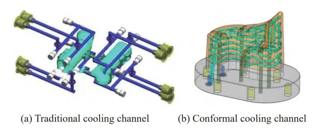
Fig. 1 Traditional cooling channel and conformal cooling channel
Due to the extremely complex and unpredictable structure of plastic parts in engineering, it is difficult for the design of conformal waterways to have relatively fixed routines and standards like traditional waterways.
The entire design process is full of uncertainty and innovation, which has aroused the great interest of many researchers. People always try to find certain rules in it to achieve the purpose of rapid design.
To achieve the rapid design of conformal waterways, researchers have proposed a series of design methods and algorithms based on various theories from different angles, and realized the automatic generation of many conformal waterway structures including spiral, Zigzag, contour, and vascular-like shapes, and have made great progress in theoretical exploration and practice.
However, most of the existing research on conformal waterway design focuses on theory and is not very operational, especially the algorithm implementation for general design platforms is rare, which cannot actually meet the actual needs of enterprises.
To improve the efficiency and quality of the design of conformal water channels for injection molds, the author, inspired by the internal duct structure of lotus roots and combining the characteristics of conformal water channels that “follow the shape of the shape”, proposed an automatic generation method for conformal water channels.
The mold parts are sliced and layered, and the control points in each layer are found in turn. The control points are connected by spline curves to generate trajectory lines, and then the cooling channel entities are formed by scanning.
The conformal water channel automatic generation system was developed on the widely used NX 3D software platform, which can quickly design the conformal water channels of mold parts.
Basic Principles
Lotus root is a common food in daily life. As shown in Figure 2a, it grows in the mud at the bottom of the water. Lotus is the flower of the lotus root, which blooms on the water’s surface.
If you cut the lotus root along the cross-section, as shown in Figure 2b, you will find that the inside of the lotus root is not solid but has many through holes, which are called ducts.
The ducts are roughly evenly distributed on the cross-section of the lotus root and do not interfere with each other. They run through the entire lotus root.
Their free shape changes with the changes in the contour of the lotus root. Just like human blood vessels, it plays the role of transporting water and nutrients to plants.
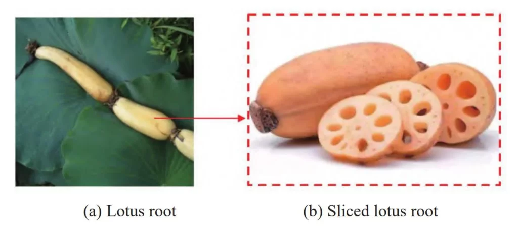
Fig. 2 Lotus root diagram
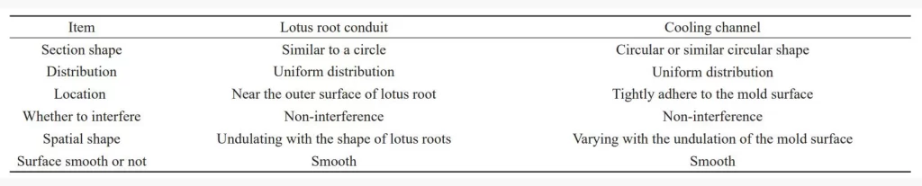
Observing the conduit structure inside the lotus root and comparing it with the conformal water channel of the injection mold, it can be found that the two are similar to a certain extent. The comparison is shown in Table 1.
The special structure inside the lotus root provides a novel idea for constructing the conformal water channel model. Considering the differences between the two, when converting the idea, it is also necessary to combine the actual situation of the injection mold cooling system design and pay attention to several key issues:
(1) Uniform distribution. From the cross-section, the lotus root conduit is evenly arranged and as close to the outer surface as possible; the conformal water channel can only achieve the best cooling effect when it is evenly arranged around the mold surface.
(2) Avoid interference. No matter how small the space of the lotus root conduit is, there is no interference between each other. Similarly, the conformal water channel cannot interfere or cross.
(3) Bending. All the conduits of the lotus root are arranged in parallel from bottom to top and are not connected; the conformal water channel needs to implement a series structure to form a cooling channel, so the connection problem at the end of the water channel must be considered.
(4) Conformal. The overall spatial shape of the lotus root duct changes with the shape of the lotus root; the conformal water channel also needs to take this into account to achieve the best cooling effect.
(5) Inlet and outlet settings. The conformal water channel needs to set the position of the inlet and outlet to meet the needs of the mold engineering.
Basic idea
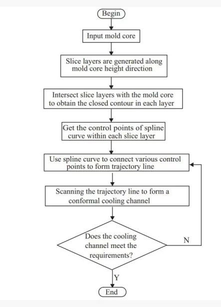
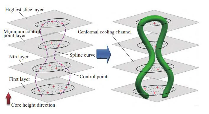
Inspired by the internal structure of the lotus root, a method for automatically generating conformal cooling channels is proposed. The basic idea is shown in Figure 3:
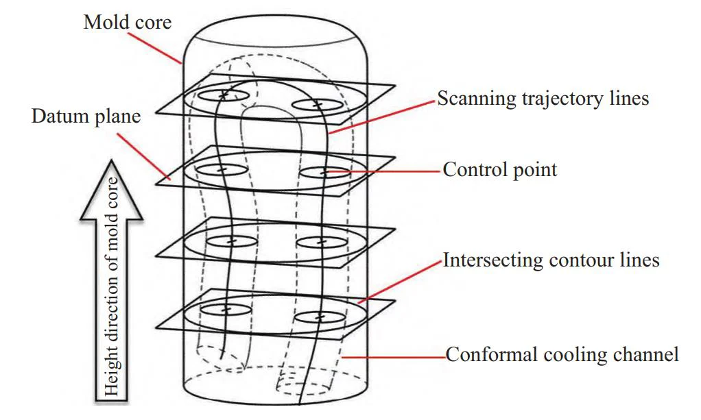
Step 1: Establish a series of reference planes along the height direction of the mold core as slice layers;
Step 2: Intersect the reference plane with the mold core to obtain the intersecting contour lines on each slice layer;
Step 3: Obtain the control points on each slice layer through interference inspection;
Step 4: Use spline curves to connect the control points on each slice layer in sequence to form a scanning trajectory line;
Step 5: Select the scanning trajectory line and use pipeline scanning to form a conformal cooling channel;
Based on this basic idea, a series of complex algorithms can be designed to realize the automatic generation of conformal cooling channels. The entire generation process of the system is shown in Figure 4.
When designing a specific algorithm, the following issues need to be considered:
1. Selection of trajectory line
Since the cooling channel is generated by pipeline scanning, the trajectory line is required to be smooth as a whole. If the method of adding straight line segments to circular arcs is adopted, the complexity of the algorithm will inevitably increase.
Spline curves are smooth curves that pass through a series of control points, and the shape of the curve can be controlled by these points.
Using spline curves as scanning trajectory lines can not only reduce the complexity of the algorithm and facilitate operation, but also facilitate 3D printing because the pipes scanned according to the spline curves have no sharp transitions.
2. Acquisition of control points
In the case of a specified pipe diameter, it is necessary to calculate all the control points that meet the requirements for subsequent connection operations.
The acquisition of control points must follow the principle of non-interference, that is, the circle generated according to the control points cannot interfere with the contour line, let alone the existing circle.
3. Connection operation
On the premise that the control points of each layer have been calculated, facing the specific situation of different numbers of control points in each layer, what kind of connection strategy is used by the spline curve command to connect these control points is the key to the success or failure of cooling channel generation.
Among them, the acquisition of control points at each layer and the selection of connection strategy are the core parts of the entire algorithm, which will be explained in detail below.
Key algorithms
1. Algorithm for acquiring control points of spline curves
The traditional method of acquiring control points of spline curves requires a series of operations such as frequent sketching and distance measurement.
The process is time-consuming and cumbersome. An automatic acquisition method is proposed to quickly detect the control points that meet the requirements. Its principle is shown in Figure 5.
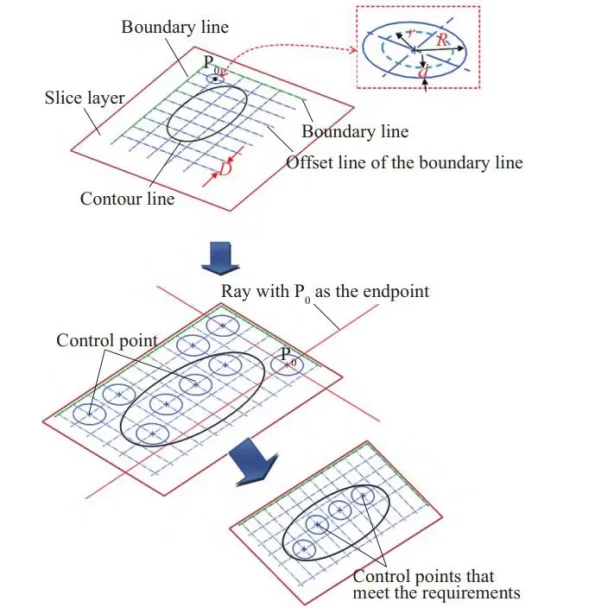
Step 1: Draw two boundary lines on the slice layer. These two boundary lines should be located outside the contour line;
Step 2: Offset the generated boundary lines respectively to obtain a series of offset lines;
Step 3: Draw a circle with the intersection of the offset lines as the center and the specified value as the radius:
(1) Determine whether the circle intersects with the contour line;
(2) Determine whether the current circle intersects with the existing circle.
Step 4: Draw a ray with the current center of the circle as the endpoint, and determine the intersection with the contour line by ray detection method;
Step 5: Determine whether the sphere with the center of the circle is exposed outside the entity.
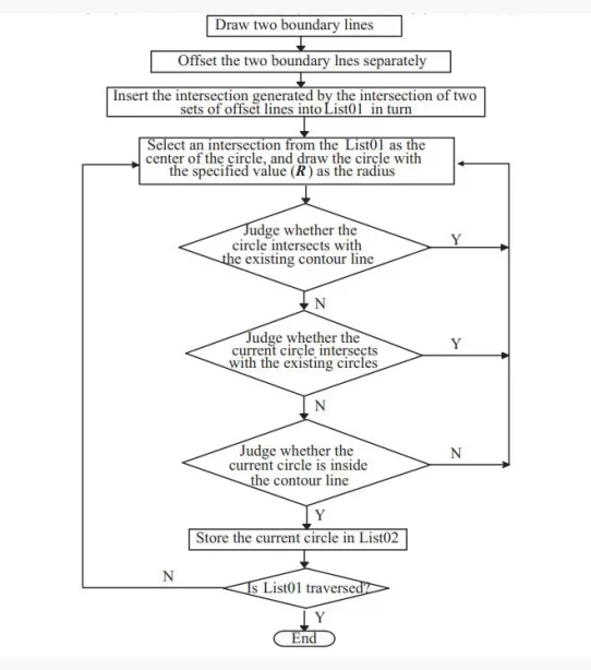
The specific algorithm flow is shown in Figure 6. According to the actual situation of mold design, five points should be paid attention to during programming:
(1) The two boundary lines on each slice layer should be outside the maximum contour line to ensure the accuracy of the result.
(2) The offset value (D) of the boundary line should be reasonably selected. If the value is too large, the result will be inaccurate; if the value is too small, the algorithm time will be increased.
(3) The intersection point used as the center of the circle should be selected in the order of intersection of the two sets of offset lines to ensure the accuracy of the result.
(4) When performing an intersection interference check, the radius of the circle is R = r + d, as shown in Figure 5, where r is the diameter of the conformal waterway; and d is the safety distance.
(5) The principle of the ray detection method to determine whether a known circle is within the contour line is shown in Figure 5, that is, with the center of the circle (P0) as the endpoint, ray detection is performed along the +X direction, -X direction, +Y direction and -Y direction respectively. If all four rays intersect with the contour line, the circle is within the contour line, otherwise it is not within the contour line.
(6) The control points obtained after the curve interference check need to be further checked to see if they are within the insert entity.
By generating a sphere with a radius of 0.5 mm with the control point as the center, we can determine whether the point is a suitable control point by judging whether the sphere and the solid can be summed.
2. Automatic connection algorithm for cooling water path trajectory
After obtaining the control points in all slice layers, the next step is to use spline curves to connect these control points in sequence to form a scanning trajectory.
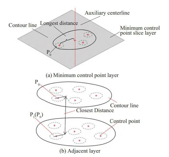
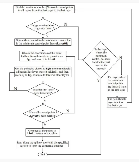
To achieve a good cooling effect, the connection strategy adopted is to first find the minimum number of points in all slice layers, start from the minimum number of points layer, find the closest control points in the adjacent slice layers in sequence, and finally connect these control points.
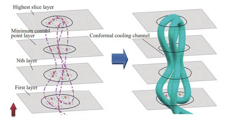
The entire trajectory line folds and passes along the core height direction. The basic idea is shown in Figures 7 to 9.
control point layer and adjacent layer control points
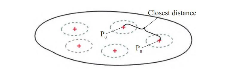
Step 1: In the slice layer with the minimum number of control points, find the control point farthest from the auxiliary center line as the base point P0, as shown in Figure 7a.
Step 2: In the adjacent layers, according to the principle of the closest distance, as shown in Figure 7b, find the control point P1 closest to the previous base point P0 in the adjacent slice layer in turn, and use it as the base point P0 again
Step 3: Determine whether the number of remaining points in the minimum point layer is >1:
(1) If ≤1, as shown in the left figure of Figure 8, go to step 4;
(2) If >1, as shown in the left figure of Figure 9, go to step 2 and continue searching for control points.
Step 4: Use spline curves to select all control points in turn to generate cooling water channel trajectory lines.
Step 5: Scan along the trajectory line with the specified section to generate a conformal water channel, as shown in the right figure of Figure 8 and the right figure of Figure 9.
It should be noted that:
(1) The position of the auxiliary centerline determines whether the entire conformal waterway will be close to the mold surface. According to the actual mold waterway, it can be set at the center of the mold core coordinates;
(2) When the trajectory line needs to bend and change direction in the highest floor or the first floor, the corresponding next control base point P0 in the same floor is selected according to the principle of the closest distance, as shown in Figure 10, to avoid interference between pipes and to achieve uniform layout as much as possible. The detailed algorithm flow is shown in Figure 11.
System interface design
UG NX is a mold design software developed by Siemens, Germany, with powerful 3D modeling, simulation and analysis functions. It can help manufacturers quickly design high-quality and efficient molds and optimize production processes.
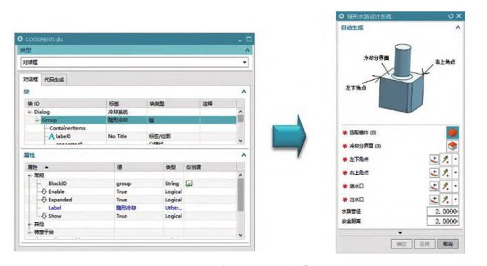
Based on the NX OPEN API interface, the conformal waterway automatic generation module is developed using Python language, and the system interface is designed using the NX secondary development tool BLOCK UI Styler style editor, as shown in the left figure of Figure 12.
The system operation interface is shown in the right figure of Figure 12.
On the operation interface, “Select insert” refers to selecting the mold insert to be cooled;
“Cooling interface” refers to the interface between the insert base and the mold surface;
the selection of “lower left corner point” and “lower right corner point” must ensure that the rectangular range they form can cover the projection of the mold surface on the cooling interface;
“water inlet” and “water outlet” are located on the bottom of the insert and need to be specified manually;
“water channel diameter” refers to the diameter of the cooling channel;
“safe distance” refers to the minimum distance between the water channel and other components inside the mold.
The user selects each parameter in turn and clicks OK, and the system can automatically generate a conformal water channel.
Application examples
Electronic cigarettes are emerging consumer electronic products. The market has a large demand for electronic cigarette shells and has strict quality control requirements.
Traditional straight pipe water channels cannot provide good cooling effects for electronic cigarette molds. In real projects, designers often need to design conformal water channels inside the mold to ensure the molding quality of plastic parts.
Based on all the proposed algorithms, a conformal waterway automatic design system was developed on the NX10.0 platform to verify the conformal waterway design of electronic cigarette molds.
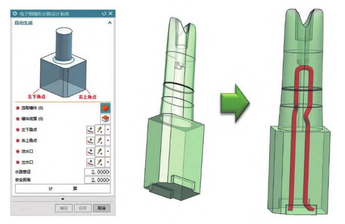
The basic size of the molding part of Example 1 is about 10 mm×20 mm×34 mm, there is an irregular blind hole in the middle of the molding part, the depth is about 24 mm, and the base size is about 14 mm×23mm×35 mm.
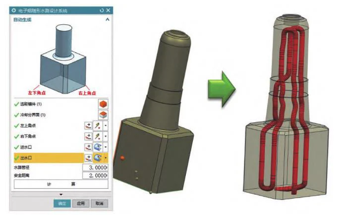
The maximum outer diameter of the molding part of Example 2 is about 30 mm, the minimum is about 15 mm, the height is about 67 mm, the depth of the concave hole in the middle of the molding part is about 6 mm, and the base size is about 40 mm×45mm×106 mm.
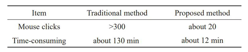
According to the traditional design method, designers need to frequently use curve editing commands such as drawing lines, rounding, and trimming to manually design conformal cooling channels in a small mold space, and must also pay attention to interference problems in real time, which is time-consuming and laborious.
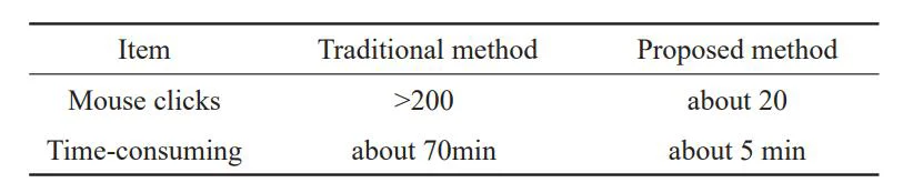
If the automated program developed by the author is used, as shown in Figures 13 and 14, the conformal cooling channel of the mold can be quickly generated by simply entering the necessary parameters. The effects of the two methods are compared in Tables 2 and 3.
Conclusion
With the in-depth application of 3D printing technology in the field of mold manufacturing, the design of conformal cooling channels has attracted more and more attention in the practice of mold design engineering. According to the existing traditional design methods, the design process of conformal cooling channels inside molds is very time-consuming and cumbersome.
To solve the existing problem of rapid design of conformal waterways, a conformal waterway automatic generation method was proposed, inspired by the internal duct structure of lotus root.
A special design system was developed based on NX as the application platform to implement all the proposed algorithms.
Verified by actual engineering cases, this method can greatly shorten the design time and improve the design efficiency of conformal waterways, and has certain engineering application value.