Improve Designs for Injection Molded Parts
Injection molding is a widely adopted manufacturing method for efficiently producing large quantities of identical plastic components with precise tolerances. This process involves melting thermoplastic flakes or pellets, which are then injected into a mold. After the molten plastic cools and solidifies, ejector pins are used to remove the finished part from the mold. Injection molding finds extensive use in various consumer products, ranging from everyday items like phone chargers and Lego bricks to automotive components.
Once the mold is created, it provides engineers with a reliable way to consistently replicate intricate parts at a cost-effective rate. Consequently, the refinement of mold-making processes holds immense importance.
Importance of Design Improvement
Design improvement in plastic injection molded parts holds significant importance for several reasons:
Enhanced Functionality and Performance
Improving the design of injection molded parts can lead to enhanced functionality and performance. By optimizing injection molded part geometry, incorporating features for better structural integrity, and addressing design flaws, the overall functionality of the parts can be improved. This can result in better product performance and customer satisfaction.
Cost Reduction
Design improvements can help reduce costs associated with injection molded parts. By optimizing part geometry, it is possible to minimize material usage, resulting in material cost savings. Additionally, simplified designs and improved moldability can lead to reduced tooling complexity and production time, leading to cost savings in manufacturing.
Quality and Consistency
Design improvements contribute to improved part quality and consistency. Consistent wall thickness, proper gate placement, and venting design help in achieving uniform filling and reducing defects such as sink marks and warping. By focusing on design for manufacturability (DFM) principles, the likelihood of achieving high-quality parts consistently is increased.
Manufacturing Efficiency
Optimized designs facilitate efficient manufacturing processes. By collaborating with mold designers and considering moldability during the design phase, potential manufacturing challenges can be identified and resolved beforehand. This leads to smoother production processes, reduced downtime, and increased productivity.
Material Selection and Innovation
Design improvements enable the exploration and utilization of advanced materials and additives. With improved design features, it becomes possible to leverage materials with enhanced properties, such as increased strength, heat resistance, or improved aesthetics. This opens up opportunities for innovation and differentiation in product development.
Sustainability and Environmental Impact
Design improvements can also contribute to sustainability efforts. By reducing material waste through optimized designs, using recycled materials, or incorporating eco-friendly additives, the environmental impact associated with injection molded parts can be minimized.
Injection Mold Design Tips
Designing parts for injection molding offers product designers considerable flexibility to incorporate complex geometries. However, it is crucial for product teams to align their designs with the specific requirements of the injection molding process.
Modifying the design after the part has been manufactured poses significant challenges. Therefore, product designers must initially ensure the plastic part is designed flawlessly for injection molding. This approach minimizes the risk of tool design issues, maximizes results, and reduces costs. To create clean and functional parts, it is advisable to adhere to the following these tips for plastic injection molding design:

Inavoidable Marks
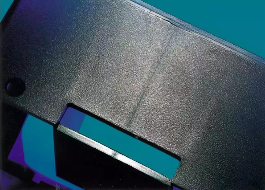
Injection molded parts have several marks that cannot be avoided, parting lines, ejection pin marks, spur marks/gate, and some fusion marks. It is important to place them in suitable locations where they don’t interfere with appearance or function. That is a very important job when designing a mold injection part. Every molded part will exhibit a visible parting line where the two mold halves separate, as well as ejector pin marks and gate locations. These elements are inherent to the molding process and cannot be completely eliminated. Hence, it is crucial to consider these factors during the initial part design phase to avoid any negative impact on the aesthetics or structural integrity of the part.
Plastic Shrinks
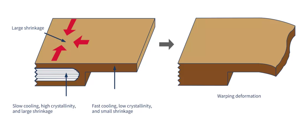
Additionally, it is important to account for material shrinkage during the cooling process. This phenomenon occurs as the material cools and can affect the dimensions of the part. To ensure dimensional integrity, the tool build should consider the expected shrinkage. It is also essential to prevent the part from getting stuck in the mold due to the material shrinking around steel features. By considering these factors during the design process, the potential issues associated with material shrinkage can be mitigated.
Maintain Consistent Wall Thicknesses
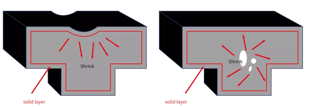
Managing mold thickness is a fundamental principle in injection molding part design. Non-uniform wall thicknesses can lead to issues such as warping or sink marks during the cooling of the thermoplastic material. Recommended wall thicknesses differ based on the type of plastic utilized. For instance, polyurethane (PUR) typically has a uniform wall thickness that ranges from 0.080 to 0.750 inches, while polystyrene (PS) has a narrower range of 0.035 to 0.150 inches. A general guideline suggests keeping wall thickness between 1.2mm and 3mm for optimal results.

When designing parts with varying thicknesses, it is essential to ensure smooth transitions between them. This promotes the uniform flow of the molten plastic within the mold cavity. One effective approach is incorporating a chamfer or fillet that is three times as long as the thickness difference.
In some cases, complex geometries necessitate thicker sections in the injection mold design. However, these sections can lead to defects like warping and sinking. To address this, product designers can hollow out these thicker sections while adhering to the prescribed wall thickness limitations. Including ribs in the part helps reinforce the hollowed sections and provide structural rigidity.

The appropriate thickness of ribs depends on the specific thermoplastic being used. Generally, ribs should be less than two-thirds of the main wall thickness to avoid sink marks on the outer surface caused by excessive rib thickness.
Eliminate Unimportant Undercuts
Undercuts in injection-molded parts refer to features that hinder the clean ejection of the part from the mold without causing structural damage. Undercuts can take various forms, such as holes, cavities, or areas where alignment deviates from the mold’s parting line. Ideally, product designers should strive to avoid undercuts altogether, as they increase the complexity, cost, and labor intensity of the injection mold design unnecessarily.
However, there are a few design strategies to address undercuts when they cannot be avoided entirely. One approach is to adjust the parting line of the mold so that it intersects with the undercut. This method is applicable mainly to designs with undercuts on the exterior of the mold.
For flexible features and materials, another option is to utilize bumpoffs or stripping undercuts. Bumpoffs involve designing a feature that can expand and deform over the mold during ejection. It is important to position the bumpoff away from the mold’s support structures and ensure it has a lead angle ranging from 30 to 45 degrees.
As a last resort when undercuts cannot be eliminated through design changes, side-actions or lifters can be employed. Side-action cores are perpendicular inserts that slide in and out of the mold as it opens and closes. However, it is important to note that these mechanisms significantly increase cost and complexity. Even with these solutions available, designers are advised to steer clear of undercuts whenever possible and eliminate undercuts during the prototyping phase.
Make Room for Draft
By incorporating a slight taper, typically referred to as a draft angle, in the part design, the ejection process from the mold can be significantly improved. This is particularly beneficial for reducing scraping and friction between the finished product and the mold. As a result, the surface of the part remains undamaged, and the overall manufacturing process proceeds more efficiently.
Understanding a draft is as simple as envisioning an ice cube tray. When ice cubes are formed and removed from the freezer, there is no need to forcefully pry them out of their individual molds using a tool. This is because the part design of the ice cube tray includes a certain degree of the draft, allowing the cubes to effortlessly pop out when subjected to slight pressure. Similarly, incorporating drafts in injection molded parts enables smooth ejection from the mold, streamlining the production process. The typical draft angle is 1~3 degree.
Conclusion
In conclusion, improving designs for injection molded parts is of utmost importance in achieving optimal results in terms of functionality, cost efficiency, quality, and sustainability. By carefully managing factors such as wall thickness, draft angles nominal wall thickness, undercuts, and material shrinkage, product designers can create parts that are suitable for the injection molding process.
The pursuit of improved designs for injection molded parts enables manufacturers to meet customer expectations, enhance product performance, reduce manufacturing costs, and contribute to sustainability efforts. By embracing design improvements, product designers can unlock the full potential of injection molding and create high-quality plastic parts that are integral to numerous consumer products in our daily lives.