Typical crankshaft parts machining process analysis and special milling fixture design
The crankshaft is one of the most important parts of a diesel engine, and its processing and manufacturing quality directly affects the normal work and life of a diesel engine.
The crankshaft mainly consists of the crankshaft front end, main journal, connecting rod journal, crank, balance block, crankshaft rear end, etc. Its main role is to the piston connecting rod group to transfer the gas pressure into torque external output, it can drive the internal combustion engine gas distribution mechanism and a variety of other accessories.
The crankshaft’s working environment and force conditions are very complex, and it is subjected to periodic changes in gas pressure, centrifugal force, inertia force, and other composite effects, so in the processing and manufacturing of the crankshaft parts of the dimensional accuracy, positional accuracy, and surface roughness have high requirements.
In this paper, through the typical crankshaft parts machining process analysis and the design of a special milling keyway fixture, improve the efficiency of crankshaft parts machining, and reduce labor intensity, to ensure the accuracy of parts processing.
Crankshaft parts machining process analysis
1. Analysis of the technical requirements of the parts
Figure 1 shows the workpiece processing elements are more: turning Φ28mm, Φ50mm, Φ 42mm outer circle and C1, C2 chamfer and R1, R5 arc.
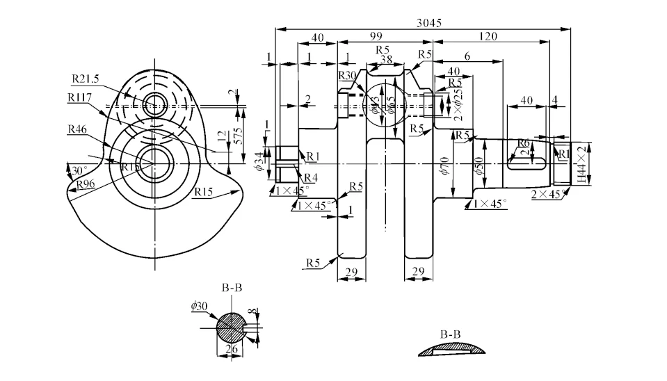
R1 and R5 arcs; drilling Φ6 inclined oil holes, Φ4 30° inclined holes in the connecting rod journal, and Φ25 holes; milling the crank side, connecting rod journal, left end face, and right end face; grinding Φ70 cylindrical surfaces; tapping 2 × G1 /2; the angle requirement at each chamfer.
Angle requirements at each chamfer, size requirements at each chamfer, the radius of the fillet is 3mm if not marked; Left end face of the part is the datum for design and machining in the length direction; High surface quality is required for some parts; The blanks are normalized to achieve high quality.
Blanks should be normalized to enhance their hardness, and improve plasticity and toughness; taper line gauge color check the taper, to determine the close surface greater than 70%.
According to the analysis, the part is complex, including turning, milling, drilling, and tapping processes, to ensure the machining accuracy and improve the machining efficiency, it is necessary to reasonably formulate the machining process and the design of special fixtures.
According to the structural characteristics of the crankshaft, the principle of unity of reference is adopted to ensure the coaxiality of the journals, i.e., the top hole is used as the locating reference for roughing and finishing machining of the main journals. When roughing and finishing Φ65 connecting rod journals, two Φ70 spindle journals are used as the positioning reference.
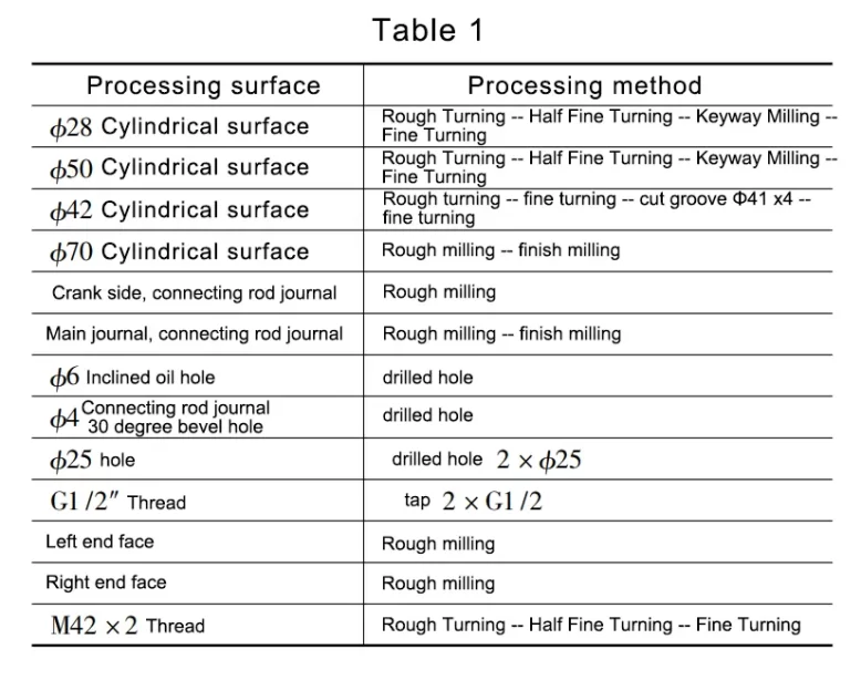
To reduce the number of clamping, to avoid multiple clamping caused by low efficiency and poor accuracy, the main machining equipment selection of the turning center. The selection of processing methods should consider the characteristics of each processing method, processing accuracy, surface roughness, and the economy of various processing methods. A comprehensive consideration of various factors of surface processing methods is shown in Table 1.
2. Preparation of process routes
Following the basic principles of “benchmark first”, “coarse first, then fine” and “main first, then secondary”, the preliminary process program is formulated as follows.
Process 10 Casting
Process 20 Normalizing
Process 30 Turning end face, punching center hole
Process 40 Rough turning the outer circle and side of crank R96.
Process 50 Rough turning the outer circle and end face of the long shaft end
Process 60 Rough turning taper 1:10
Process 70 Rough turning short shaft end cylindrical and face.
Process 80 Semi-finish turning of short shaft end cylindrical and end face
Process 90 Semi-finish turning of short shaft end and end face
Process 100 Semi-finish turning long shaft end and face
Process 110 Precision turning of short shaft end and end face
Process 120 Crank side milling
Process 130 Milling connecting rod journals
Process 140 Drilling 2 × Φ25 holes
Process 150 Tapping 2 × G1 /2″ threads
Process 160 Drill 2 × Φ6 diagonal oil holes
Process 170 Drill 30-degree inclined hole Φ4 in connecting rod journal
Process 180 Inspection
Process 190 Surface hardening
Process 200 Rough grinding main journal
Process 210 Milling long shaft end keyway
Process 220 Milling long shaft end keyway
Process 230 Grinding taper 1: 10
Process 240 Rough grinding of connecting rod journals
Process 250 Fine grinding of connecting rod journals
Process 260 Fine grinding of the main journal
Process 270 Turning retract grooves
Process 280 Turning thread M42 × 2
Process 290 Deburring
Process 300 Inspection
Process 310 Cleaning, oil sealing, and warehousing
Keyway milling fixture design
1. Design analysis
To design a keyway milling fixture for milling a 12 × 40 mm keyway in Process 210, it is necessary to limit the workpiece to 6 degrees of freedom.
When milling the keyway, the long journal of the crankshaft has already been machined. Therefore, the centerline of the two end faces of the crankshaft is selected as the main positioning datum for machining, and two V-block positioning are used to limit the movement and rotation of the X-axis and Z-axis of the workpiece, the clamping shaft is used to limit the movement of the Y-axis on the right end face of the crankshaft, and the positioning block is used to limit the rotation of the Y-axis at the journal of the connecting rod.
This positioning method can make the 6 degrees of freedom of the workpiece completely restricted, at this time the crankshaft belongs to the complete positioning, and the positioning program is feasible.
Therefore, the positioning element of the fixture is a V-block, and the clamping element is an adjustable support and platen.
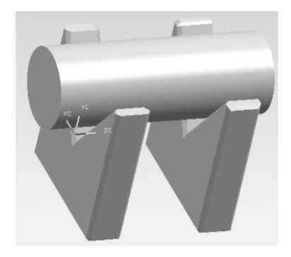
The positioning elements are shown in Fig. 2. Because of the poor flexibility of the wide V-block, the long processing time, the complexity of the machining process, and the material consumption, two narrow V-blocks are used instead of the wide V-block, and the role of the two narrow V-blocks is the same as that of the wide V-block.
Clamping element as shown in Figure 3, the designed clamping element meets the design principle of a clamping device, relatively simple structure, easy to process, easy to operate, good performance, and can ensure sufficient clamping stroke.
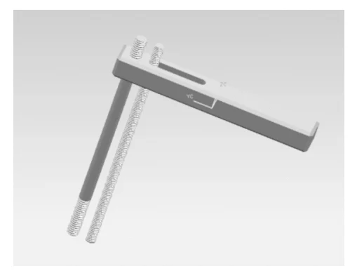
The power source of this clamping element is manual clamping, the user uses a wrench to adjust the nut on the support to control the height of the pressure plate, thus changing the size of the compression force.
2. Design of keyway milling fixture
Based on the above analysis, design the keyway milling fixture as shown in Fig. 4.
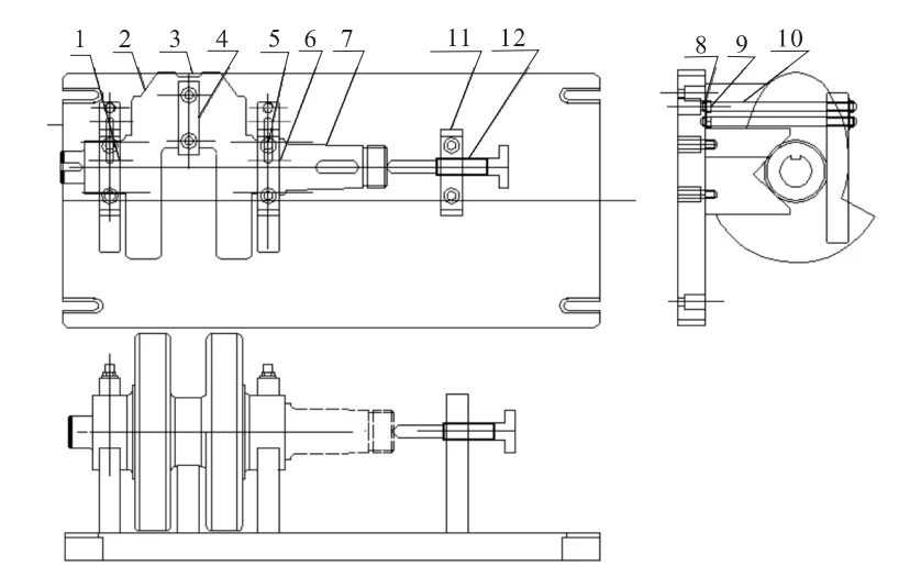
Bolt the two V-block, locating the block and supporting block to the clamping body, then fix the clamping body in the T-slot of the guide rail of the table through the T-block, place the two Φ70 spindle journals of the crankshaft on the V-block (the movement and rotation of the crankshaft in X-axis and Z-axis are restricted), the connecting journal shaft is in contact with the locating block (the rotation of the crankshaft in Y-axis is restricted), and then rotate the top of the clamping shaft to make the top part of the clamping shaft contact with the top hole of the crankshaft (the rotation of the crankshaft in Y-axis is restricted). Rotate the top of the clamping shaft so that the top portion of the clamping shaft is in close contact with the top hole of the crankshaft (movement of the crankshaft in the Y-axis is limited), press the two platens against the Φ70 main journal of the crankshaft, and control the crankshaft on the clamping body by tightening the screws.
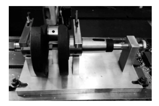
When disassembling, loosen the screws on the two platens, rotate the platens to a certain angle, rotate out the clamping shaft, and take out the crankshaft (see Fig. 5). This fixture has a simple structure, is easy to disassemble and install, and greatly improves the positioning accuracy and efficiency of parts machining.
Conclusion
Through the study of the technical requirements of crankshaft parts, processing methods, and machining process programs, for the processing of similar complex parts to provide a certain reference. The designed Process 210 keyway milling fixture is easy to operate and has high machining accuracy, which has been practically applied and achieved great economic benefits.