What is a U-drill?
The U-drill is a widely used indexable tool for hole machining in the mechanical industry. It drills holes with a depth-to-diameter ratio (L/D) generally in the range of 1.5-3.0, and it is also known as a shallow hole drill.
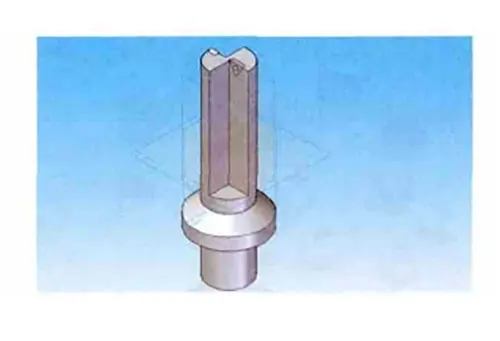
This drill was initially developed by the Swedish Sanvik dormant company in the 1970s. It is a new type of U drill (shown in Figure 1) characterized by fast cutting speed, large feed, and high productivity.
Compared with the twist drill, cutting time can be reduced by 80%, and cutting efficiency is 5-10 times higher when used in CNC machine tools. Not only drilling but also the return trip to the hole, not only in the lathe, milling machine, machining centers, and other machine tools have been widely used, but also in the combination of machine tools and automated lines, have been excellent applications.
It can be used for drilling, molding, or reaming, making it ideal for hole machining.
Structural characteristics
The basic structure of the U-drill consists of indexable inserts, clamping elements (screws), blades and supporting parts (coolant supply system, connecting devices for various equipment) as shown in Figure 1.
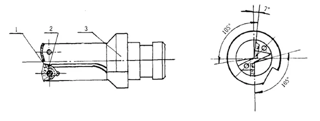
It adopts the press-hole structure. The indexable insert with reasonable geometric parameters of the chip-breaking mechanism is fastened to the front end of the cutter body with the clamping element, and screws, which constitute the cutting part of the drill.
The cutter body has two chip removal grooves and a hole to deliver coolant to the cutting area. The end of the cutter body can be made into a straight or tapered shank for connection with different equipment.
1. Indexable Inserts and Clamping Methods
Currently, the commonly used carbide indexable inserts in U-drill are triangle, quadrilateral, rhombus unequal hexagonal, etc. They all have screw holes and about 7° back angle, among which unequal hexagonal (also called convex triangle) inserts are used the most.
Most of the indexable inserts are clamped with tapered screws because the inserts and screw holes are offset from the center of both (generally 0.15~0.2mm); screwing the screws produces a downward compression and tightening to the positioning surface of the force, which firmly presses the inserts.
The number of blades used in indexable drills is mainly related to the diameter of the tool. In general, two blades are used for diameters of 17.5~856mm.
2. utter structure
The key to U-drill manufacturing is the tool body structure. Whether the tool body structure is reasonable or not directly affects the manufacturing quality of the U-drill.
Therefore, whether designing or processing, we pay much attention to the body structure of U-drill. Generally speaking, the body structure of the U-drill mainly refers to the chip conveyor, insert groove, coolant hole, positioning shoulder, and clamping surface.
2.1 Chip conveyor of U-drill
The chip former of the U-drill has two forms: straight groove and spiral groove. Generally, the straight groove is used when the drill is not rotating; when it is rotating, the straight groove or spiral groove is used. The chip former of the U-drill directly impacts the strength of the body.
Therefore, the following conditions must be met.
①High resistance to torsion and bending deformation.
(ii) Optimized cutting flow space; and
Optimized cutting flow space; ③ Optimal coolant injection position and flow space.
2.2 U-drill insert cross-section
The insert groove of a U-drill is located at the front end of the tool body, where the insert is fixed. Its position and angle directly influence the cutting performance of the U-drill. Generally speaking, the insert groove of the U-drill must meet the following conditions.
① Inside and outside the center of the two cutting inserts, high control is strict, especially the inner cutting insert shall not be higher than the center, generally lower than the center of 0.15 ~ 0.2mm;
② Inside and outside the two cutting inserts, reasonable sharing of cutting volume generally cut the entire cutting volume of the inner teeth about 1 / 3, the outer teeth cut about 2 / 3;
③ The location of the two cutting inserts should make the radial component of the cutting force to balance each other;
④ blade groove positioning surface, support surface should be resistant, have a certain hardness HRC45 ~ 50, roughness is minor, generally below 0.8.
2.3 Coolant system
The purpose of using coolant in the U-drill is to make it cooled, lubricated, and effective. Therefore, the U-drill must ensure a certain pressure and coolant flow rate in the use process.
The coolant hole must meet the following conditions.
① The central coolant hole should be as large as possible; the hole should be smaller to meet many coolant inputs and pressure.
② The outlet hole should have a reasonable injection position to ensure the best cooling effect.
Theoretical Analysis
1. Mechanical analysis
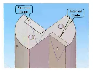
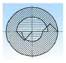
The blade shapes used in a U-drill are quadrilateral, trilateral, and hexagonal. Two blades with a diameter of 18 mm are usually installed on the 50U drill, and the inner and outer blades are overlapped to divide the processed aperture into four parts and two steps (see Figure 3).
However, when the inner insert is not the center of rotation of the drill, if a trilateral insert is used (T-shaped), only the cutting force Fq and the feed force Fj are generated in the drilling (see Fig. 4), and there is no back force.
The feed force affects the design of the machine’s feed mechanism and the selection of the cutter body’s bending strength; the asymmetric distribution of the two inserts results in a radial combined force FH and a circumferential combined moment TH in the cutter body (see Figure 5).
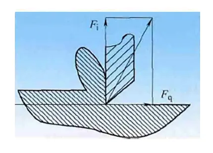
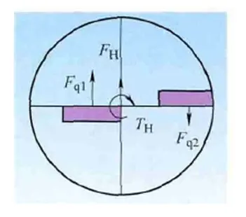
Figure 5 Force composite diagram
The radial combined force is likely to cause the actual drilling axis to deviate from the theoretical machining route, affecting the dimensional and form tolerances of the machined hole; the circumferential combined moment can be balanced by matching the rotating torque of the machine tool, preventing the drilling body from fracturing.
Therefore, minimizing the radial force FH during machining becomes a key issue in designing and manufacturing shallow hole drills.
2. Mathematical analysis
To facilitate the force analysis of the U-drill, the position of the outer edge and the position of the inner edge were moved to the same side for consideration (without considering the amount of overlap first) (see Figure 6). The force of T-shaped insert drilling is similar to the blank end face grooving.
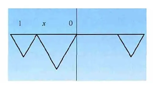
According to the metal cutting mechanism, the cutting force of a U-drill insert is proportional to ap (backdraft), f (feed), and v (cutting speed).
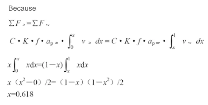
The mathematical model of the drilling force is established according to the principle of calculus as follows (see Figure 7).
Advantages
(1) The U-drill can drill holes on surfaces with an inclination angle of less than 30° without reducing the cutting parameters.
(2) After the U-drill’s cutting parameters are reduced by 30%, intermittent cutting, such as machining intersecting holes, can be realized.
(3)U-drill can realize the drilling of multi-step holes and boring, chamfering, and eccentric drilling.
(4) The U drill can process the hole with a precision of 0.05Hm and a surface roughness value of B=1.64n. It can also realize high feed, high speed, and high-efficiency cutting.
(5) U-drill drilling chips are primarily short, and the tool can use its internal cooling system for safe chip removal without cleaning the chips on the tool. This is conducive to the continuity of product processing, shortening processing time and improving efficiency.
(6) Under the standard length-diameter ratio, chips need not be retreat when using a U-drill to drill holes.
(7) The U-drill is an indexable tool, so it is easy to replace the blades without sharpening after wear, and the cost is low.
(8)The surface roughness of the hole processed by the U-drill is minor, and the tolerance range is small so that it can replace the work of some boring tools.
(9) When a U-drill is used without pre-punching the center hole, the bottom surface of the processed blind hole is relatively straight, eliminating the need for a flat-bottom drill.
(10) U-drill technology reduces the number of drilling tools. Because the U-drill adopts headset carbide inserts, its cutting life is more than ten times that of an ordinary drill.
At the same time, the inserts have four cutting edges. The inserts can be replaced whenever the blade is worn out and cut. The new cutting saves a lot of time grinding and replacing the tool and improves the efficiency of the work by an average of 6 to 7 times.
Common problems
(1) The blade is damaged too quickly and easily breaks, increasing machining costs.
(2) A harsh whistling sound is emitted during machining, and the cutting state is abnormal.
(3) The machine tool vibrates, affecting the machining accuracy of the machine tool.
Tips for using U-drill on CNC machine tools
(1)The rigidity of the machine tool and the alignment of the tool and the workpiece when using the U-drill are high, so the U-drill is suitable for use on high-power, high-rigidity, high-rotation speed CNC machine tools.
(2)When using a U-drill, the center blade should be selected with good toughness, and the peripheral blades should be chosen with sharper blades.
(3) processing of different materials should be used in different groove-shaped inserts, in general, small feed, small tolerances, U drill L/D ratio is large, the selection of cutting force smaller groove-shaped inserts, and vice versa, roughing, tolerances, U drill L/D ratio is small, the selection of cutting force is more extensive groove-shaped inserts.
(4) The use of U-drill must consider the machine tool spindle power, U-drill clamping stability, cutting fluid pressure and flow, while controlling the effect of U-drill chip removal, otherwise it will largely affect the surface roughness and dimensional accuracy of the hole.
(5) When clamping the U-drill, be sure to make the center of the U-drill coincide with the center of the workpiece with an error of less than 2% and perpendicular to the surface of the workpiece.
(6) To adjust the center height of the U-drill, rotate it by 90° each time (the bottom plane of the U-drill drilled by the adjusted center will have a 0.5mm bump).
(7) When using the U-drill, select the appropriate cutting parameters according to the different part materials.
(8) When the U-drill test cuts are made, do not reduce the feed or speed at will out of caution and fear, as this may break the U-drill insert or damage the U-drill.
(9) When the U-drill is used for machining, and the blade is worn or broken, analyze the cause carefully and replace the blade with tougher or more wear-resistant.
(10) When using the U-drill to process stepped holes, start from the large hole first and then proceed to the small hole.
(11) When using the U-drill, pay attention to the cutting fluid, which needs enough pressure to flush out the chips.
(12)The blades used on the center and edge of the U-drill are different and must not be misused, otherwise the U-drill shank will be damaged.
(13) When drilling with a U-drill, the workpiece can be rotated, the tool can be rotated, and the tool and workpiece can be rotated simultaneously. However, when the tool is moved in a linear feed mode, the most commonly used method is to rotate the workpiece.
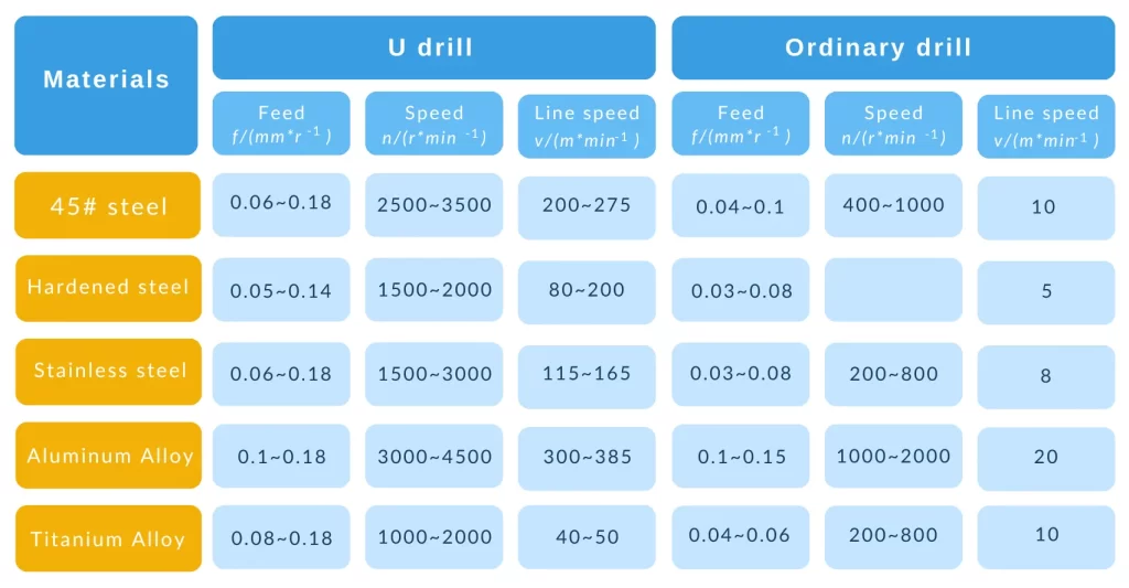
Table 1 Comparison of cutting parameters between U drill and ordinary drill
Conclusion
U-drills are widely used in material processing, especially in machining workpieces with high hardness or complex shapes.
It is usually made of high-quality steel or carbide with substantial wear and heat resistance.
The U-drill’s design is characterized by its unique cutting-edge shape, which provides high cutting efficiency and long tool life.
They are suitable for various industrial manufacturing applications, such as aerospace, automotive manufacturing, and electronics.
With the increasing requirements for precision and efficiency in industrial manufacturing, U-drills will develop towards higher cutting precision and longer tool life.
U-drills can maintain excellent performance at higher cutting speeds and under more demanding machining conditions through improved materials and coating technologies.
New high-performance materials like nano-coatings and ceramic composites may enhance their hardness, wear, and corrosion resistance.
These materials will enable the U-drill to perform better when machining difficult-to-machine materials (e.g., titanium alloys, composites, etc.).