12 Design tips for plastic injection parts
Choose the right material
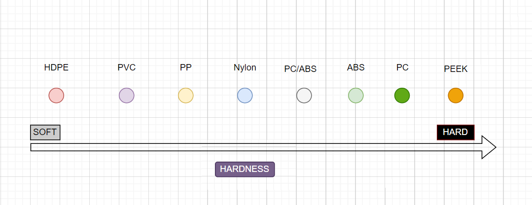
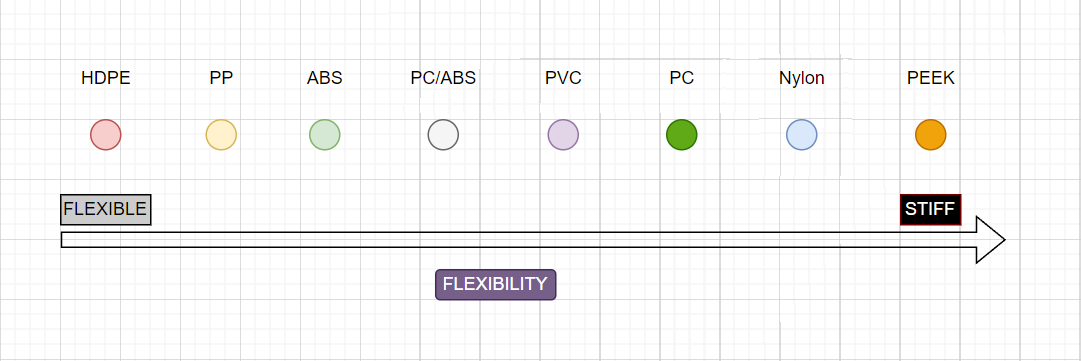
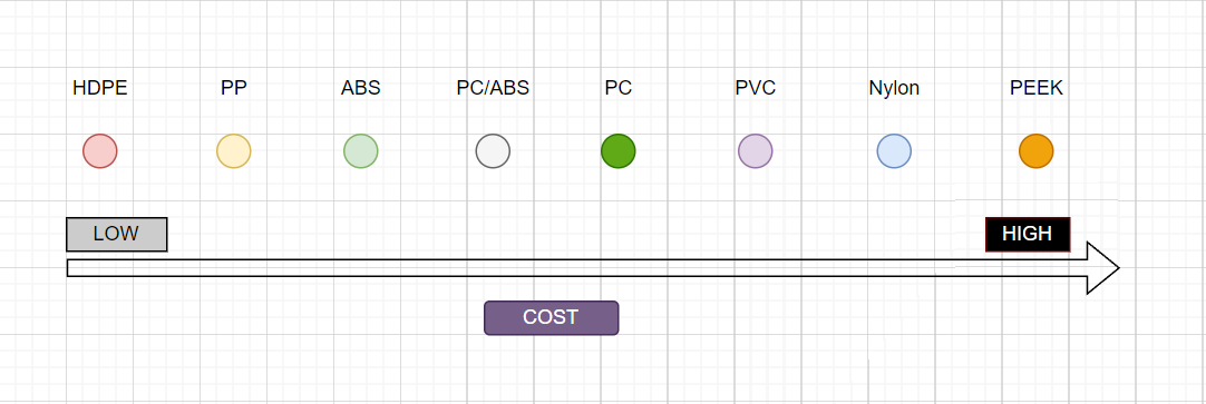
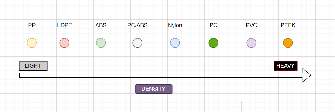
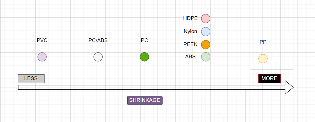
Choosing the right plastic material for injection molded parts can be tricky. Factors that need to be considered in most cases include the material’s hardness, strength, density, shrinkage, melting point, and cost. Depending on the usage scenario, it may also be necessary to consider the material’s UV resistance, chemical resistance, electrical conductivity, heat insulation, self-lubrication, impact resistance, biocompatibility, transparency, etc. Below are rankings of the general properties of some common plastics.
Where to find the information?
Comprehensive data reports for various manufacturers’ plastics can be accessed at www.ides.com.
https://www.makeitfrom.com/material-group/Thermoplastic offers an intuitive interface for obtaining general plastic properties.
Major manufacturers also offer PDF files containing information about their plastic materials. For instance, Sabic’s plastic property datasheet can be found at https://www.sabic.com/en/products/polymers.
Plastic Additives and Fillers
Plastic additives and fillers, whether organic or inorganic compounds are incorporated into plastics to alter their properties. While most plastics are naturally durable and impact-resistant, they may exhibit characteristics such as brittleness, hardness, flammability, or excessive weight, which can be unsuitable for their intended purpose. The inclusion of additives or fillers allows for the transformation of plastics to meet their intended applications while preserving the attractive qualities that initially drew attention to them. Virtually every type of plastic incorporates some form of additive to optimize its performance for its intended use.
The most common plastic additives/fillers are probably plasticizers, fiberglass, carbon fiber, and talcum.
The majority of plasticizers are esters formed through the reaction of acids with alcohols, and the quantity added has an impact on the final product. For instance, vinyl gloves contain approximately 50% plasticizers to ensure their flexibility and comfort when worn.
Fiberglass is employed to reduce plastic shrinkage while enhancing strength and stiffness. It also typically increases the density of the plastic, making it heavier. On the other hand, carbon fiber further enhances the plastic’s strength, and it is considerably lighter than glass fiber.
The application characteristics of talcum powder vary in different plastic materials. In ABS and nylon, the addition of talcum powder provides not only economic benefits but also improvements in heat resistance and molding shrinkage. In polyethylene, adding talcum powder primarily enhances rigidity, and heat resistance, reduces molding shrinkage, and lowers costs. Talcum powder finds the widest and most significant application in polypropylene, where it improves overall strength, and heat resistance, reduces molding shrinkage, and increases rigidity. Additionally, in polypropylene, high-grade talcum powder can act as a nucleating agent, effectively enhancing the comprehensive performance of polypropylene.
Numerous other plastic additives are commonly employed in the plastic injection sector. Some instances encompass lubricants, impact enhancers, flame retardants, antistatic agents, and antioxidants. It’s crucial to recognize that many plastic properties can be altered through these additives.
Plastic’s Typical Usages
Many plastics have typical applications due to some particularly outstanding properties. For example, PTFE is resistant to high temperatures and chemical resistance, so it is used for kitchen utensils coating. PP can be constantly folded and unfolded and used for the hinge of the glasses case. ABS/PC has high strength and impact resistance and is used in the shells of various electrical appliances. These typical application scenarios can be used as an important reference when selecting materials.
How To Chose the Right Material for Injection Molded Parts
There are approximately 85,000 to 90,000 commercial options available for plastic materials. This vast array can be categorized into around 45 polymer families or blends. Selecting the most suitable material for a specific project can be akin to detective work. To simplify the process, we recommend a 3 step workflow.
First, start by identifying a similar typical use of plastic, such as in the case of gears where common plastics like PEEK, POM, and nylon are used.
Next, compare the properties of these plastics, taking into account other factors that may required like high-temperature resistance or chemical resistance. This will help narrow down the material options.
Finally, consider the appropriate additives or fillers to enhance any properties that may not fully meet the requirements.
Do not tolerate unnecessary tolerances
Generally speaking, the plastic injection molding process can reach a tolerance level of +/- 0.1mm. Very tight tolerance +/- 0.025 mm is tough but still possible. Factors that affect the final product tolerance include shrinkage, warpage, and temperature changes.
The higher the shrinkage the harder to get tight tolerances. For instance, POM shrinkage is 1.5%~3%, and PC/ABS has a shrinkage of 0.6%. It is a lot easier to have a tight tolerance of a PC/ABS part than a POM part. The most common way to reduce shrinkage is to add fiberglass or carbon fiber to the plastic. Adding 30% fiberglass in nylon reduces its shrinkage from 1.5% to less than 0.5%.
The warpage is caused by internal stress, which can be reduced by proper designs. Proper aging after the product is injected can also help.
In the room temperature range, the coefficient of linear thermal expansion (CLTE) ranges between about 0.6 x 10⁻⁴ to 2.3 x 10⁻⁴ K-1 for most of the thermoplastics. Or a 50mm long thermoplastic with a temperature change of 20 degrees Celsius, its size change would be about 0.06mm to 0.23mm. This tells us that it can be quite challenging to maintain tight tolerances when the temperature changes. However, if you choose plastics with a lower thermal expansion rate, it can help in achieving and maintaining tighter tolerances.
Choose the right wall thickness and be consistent.
There are 2 principles for the wall thickness of an injection molded part. Keep reasonable thin wall thicknesses, and keep uniform wall thickness as much as possible. The reasons are as follows.
Thick Walls are Not necessary: In most cases, very thick walls are not necessary. The strength-to-weight ratio is better for a hollow pipe than a solid rod. The same principle applies to other shapes too. In other words, a very thick wall can always be replaced by a relatively hollow structure with less wall thickness but provides the same strength.
Material Usage: Thick walls mean more material and hence more material cost and possibly a larger injection machine.
Cycle Time: Thicker walls take longer to cool during the molding process, leading to longer cycle times for each part. This can slow down production and increase costs.
Warpage: Thick walls are more prone to warping and distortion as they cool and solidify. This can result in parts that do not meet the required tolerances or dimensions.
Sink Marks: As thick sections cool and shrink at different rates than thinner sections, sink marks or depressions may form on the surface of the part, affecting its appearance and surface finish. For more details on how sink marks are formed, check this article.
Injection Pressure: Molding thick walls may require higher injection pressures, which can stress the molding equipment and increase the risk of defects.
Stress Concentration: Thick walls can create stress concentration points in the part, which can make it more susceptible to cracking or breaking under load or impact.
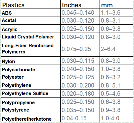
The optimal wall thickness depends on the material’s viscosity and the part’s structure. In general, the optimal wall thickness for most of the thermal plastic ranges from 1 to 4 mm. The following are the recommended wall thicknesses for some common plastic materials.
Too Thin Wall is also problematic: For a given wall thickness, the distance that the molten plastic can flow is limited. If the wall is too thin, very high pressure and temperature are needed, and the total size of the part is limited. By experience, normal plastic should not have a wall thinner than 0.03 inch or 0.75mm.
What if a Thick Wall is really needed: Other plastic molding processes are more suitable for producing parts with very thick walls. Injection-molded structural foam, gas-assist injection molding, compression molding, and reaction injection molding are all processes known for their effectiveness in making thick-walled parts.
Keep a consistent wall thickness.
Uneven wall thicknesses can cause warping because they cool and contract at different rates. If you need varying thicknesses, make sure the change doesn’t exceed 20% of the standard wall thickness and ensure a smooth or tapered transition. This will result in a better-quality part with less risk of warping.
If you still have questions about wall thicknesses, please contact CapableMachining. We have experienced engineers to answer all your questions.
Include Draft Angles in Your Design.
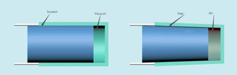
The draft angle is mainly to avoid that the product cannot be ejected due to adhesion or vacuum pressure during the mold opening process. At the same time, the draft angle can also reduce surface scratches. In most common situations, 1 ~ 2° draft angles are applied. Higher shrinkage and softer materials need a bit more draft angle. There are a few more subtleties of draft angles as follows.
Vertical faces requirements: 0.5°~1°
Most common situations: 1 ~ 2°
All shutoff surfaces: 3°
Faces with shallow textures: 1 ~ 2°
Faces with deep textures: 5° or more
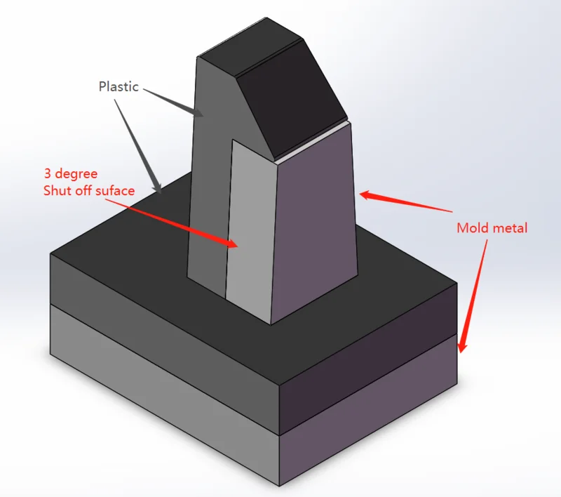
The shutoff surface angle is a special kind of draft angle. It is not applied for easier mold release but for prolonged mold lifecycles. The shutoff surfaces are the surfaces where metal rubs against metal. Figure 2 shows an example of a common snap-fit design. When the mold opens and closes, metal rubs metal on the shutoff surface. To reduce the friction especially when the two halves of the injection mold are slightly misaligned, a slightly bigger angle (3°) is suggested.
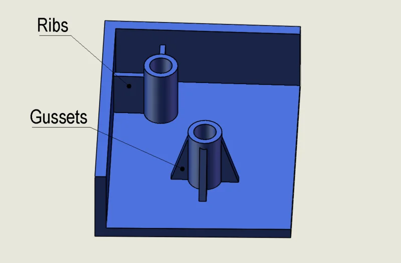
Add ribs and gussets
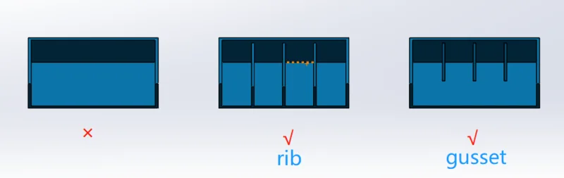
Ribs and gussets can greatly increase the structural strength of an injection molded part. A T-shaped structure is much stronger than an I-shaped structure given the same material weight. The thickness, height, and span of ribs have to be carefully considered to have the optimal result. Below are some general rules.
-
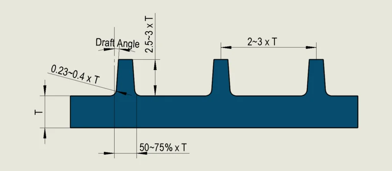
The thickness of the rib at its base should be approximately 50-75% of the nominal wall thickness.
-
The height of the rib should be approximately 2.5 to 3 times the nominal wall thickness.
-
The base of the rib should have a radius of approximately 0.25 to 0.4 times the nominal wall thickness.
The distance between two ribs should be roughly 2 to 3 times the nominal wall thickness.
When a rib connects to the main wall, there will always be a thicker area. To prevent surface imperfections (sink marks), it’s crucial to keep this thick area as small as possible. However, if the rib is too thin, it might need to be made deeper to provide enough strength, but this can lead to issues like buckling under pressure and making the mold harder to work with. Ribs injected at high pressure can also get stuck in the mold.
The curved transition area between the rib and the main wall (fillet radius) should not be too small either. It’s there to reduce stress where the rib meets the main wall. Ideally, the fillet radius should be at least 25 percent of the rib’s thickness.
The ribs themselves should generally be between half to three-quarters of the wall thickness. However, it’s best to aim for the higher end of this range when working with plastics that have low shrinkage and are less prone to sink marks.
Apply radii and fillets to the injection molded part.
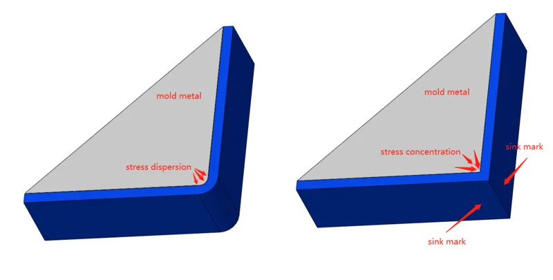
Incorporating rounded edges into injection molded parts, whenever feasible, offers several advantages. Firstly, it eliminates sharp corners, thereby enhancing both material flow and the structural integrity of the part. When plastic cools and shrinks, stress is concentrated at sharp corners. In the case of radii corners, the stress will be dispersed over a relatively long curve range, thus reducing the sink mark.
Radii and fillets also facilitate part ejection by reducing the likelihood of corners getting stuck during the ejection process compared to sharp corners.
Additionally, including sharp corners in your part design significantly increases production costs, as it necessitates the use of expensive manufacturing techniques to achieve those sharp corners in the mold.
To optimize your design, consider adding internal radii that are at least 0.5 times the thickness of the adjacent wall, and external radii that are 1.5 times the size.
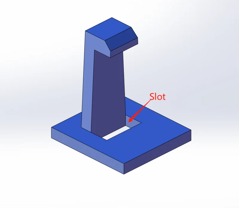
Minimize Undercuts and Incorporate Slots When Feasible.
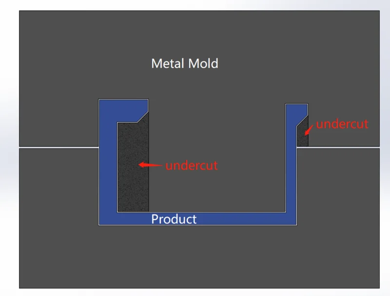
An undercut refers to a feature or area on a part’s geometry where it is not possible to remove the molded piece straight out of the mold. This is because the undercut creates a mechanical lock, preventing the part from being ejected easily and requiring complex mold design or additional mechanisms for removal.
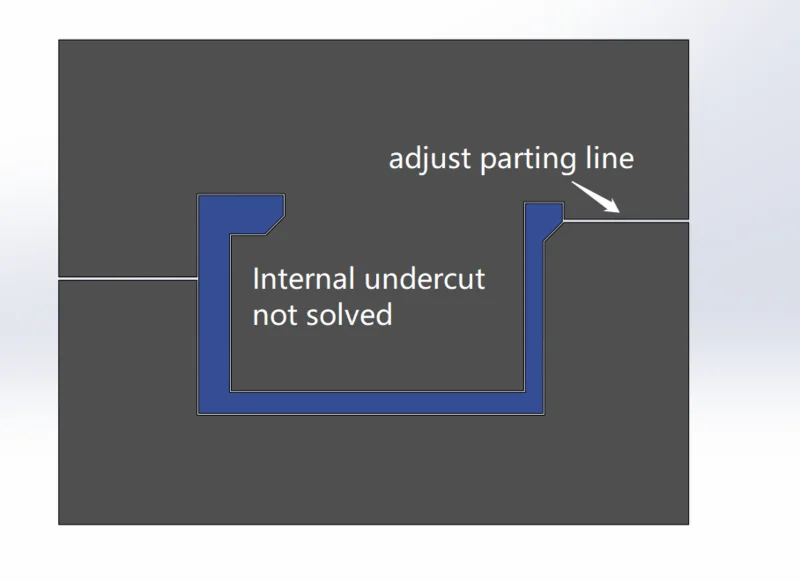
To address the external undercuts, designers can adjust the parting line of the part and make the undercuts accessible for ejection. There are other technic to deal with both internal and external undercut.
Core Pulls: Core pulls involve using hydraulic or mechanical systems to retract movable cores within the mold. These cores match the shape of the undercut. After the plastic material solidifies, the cores are pulled out of the molded part, allowing for easy release. Core pulls are effective for simple to moderately complex undercuts.
Slider Mechanisms: Sliders are mold components that move perpendicular to the mold’s opening and closing motion. They are used to push the undercut feature out of the mold during ejection. Slider mechanisms are versatile and can handle various undercut shapes but can add complexity to the mold design.
Lifters: Lifters are mechanical components that physically lift or tilt the molded part to release undercuts. They are useful for more intricate shapes and challenging undercuts but also contribute to mold complexity and cost.
Sacrificial Cores: This method involves using removable core inserts within the mold. These inserts remain inside the molded part and are removed after molding to facilitate ejection.
Bump-Offs: Bump-offs or stripping undercuts apply a slight, controlled force to the mold to help release the molded part, especially when dealing with parts that are flexible enough to deform and expand.
Other Side Actions: This category includes various side actions such as hand-load cores, unscrewing mechanisms, collapsible cores, and more. These mechanisms are used to address specific undercut scenarios and complex part geometries.
All of the above will increase the cost of the mold and the complexity of the mold. These are the last resort methods that mold designers have to deal with the undercut structure after the part design has been completed. The best method in the part design stage is naturally to avoid undercuts or add a slot under the undercuts, also called shut-off.
Secure bosses to side walls or ribs
Bosses are cylindrical standoffs molded into a plastic part to accept an insert, self-tapping screw, or pin for assembling or mounting parts. The boss is attached to the nominal wall just like the ribs. Like the ribs, in order to avoid shrinkage marks, the thickness of the roots should not be too large, so the wall thickness of the boss also needs to be controlled within the range of 50% to 75% of the nominal wall thickness. In order to ensure the strength of such a thin-walled boss, gussets and ribs are usually added to support or connect to the side panels.
Avoid deep holes and deep narrow grooves
This is mainly due to mold structure considerations. The mold structure corresponding to the deep hole is a long pin, and the narrow and deep groove corresponds to the thin sheet. These two structures have poor strength. During the injection molding process, the mold structure needs to withstand tens of thousands of impacts from the hot-melt plastic fluid. This can cause thin sheets and long pins to bend or break, and the broken parts can sometimes cause damage to other mold parts. Therefore it should be avoided as much as possible. Generally speaking, structures with a hole-depth ratio exceeding 10 and slots with a width-depth ratio exceeding 10 should be avoided.
Gate Placement: Emphasizing Part Aesthetics
To ensure the successful design and production of your injection-molded part, it’s crucial for the manufacturer to grasp your expectations regarding its appearance.
In injection molding, certain marks are inevitable, including gate marks, parting surface marks, side core marks, ejector pin marks, and more. It’s essential to have open communication with the tool manufacturer and emphasize your specific appearance preferences.
Gate marks, for instance, are the traces left where the molten material enters the mold. To avoid these marks where they’re not desired, it’s crucial to work closely with experienced manufacturers. They will judiciously select gate types, gate locations, parting surface positions, and other parameters based on your requirements to minimize these marks and achieve the desired finish for your part.
Talk to the Experts: Streamline Your Injection Molded Part Design
At CapableMachining, our seasoned team of experts has not only witnessed a wide array of plastic part designs but has also successfully tackled numerous challenges related to part design and injection molding processes. Engaging with experienced injection molding firms at the outset of your design journey can significantly streamline your path to success.
We pride ourselves on offering invaluable guidance rooted in our extensive industry knowledge. If you find yourself pondering any aspect of injection molded part design, we eagerly welcome your questions and the opportunity to provide tailored suggestions. At CapableMachining, your project’s success is our priority.