12 Tips for Designing CNC Machined Parts to Optimize Performance
Avoiding Thin Wall Thickness in CNC Machined Parts
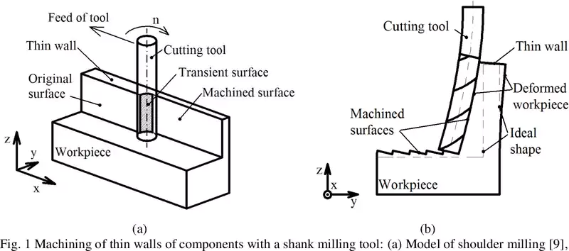
When designing parts for CNC machining, it is crucial to consider the thickness of the walls. Thin walls can pose a risk of bending and breaking during the machining process. Extensive research has shown that thin walls are prone to warping, with the top portion bending more than the bottom.
<1>
<2>
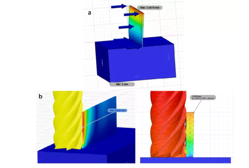
Several factors come into play when determining the extent of bending, including the thickness, height, and length of the wall, as well as the strength of the material itself. On the CNC machining side, factors such as the amount of material being removed by the cutting tool and the speed at which it moves along the wall also impact the forces involved and the cost of the parts.
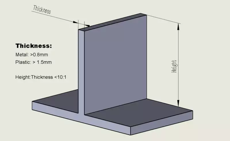
To ensure optimal performance, it is generally recommended to maintain a wall thickness above 0.8mm for most metals and 1.5mm for most plastics. Additionally, it is advised to maintain a height-to-thickness ratio below 10:1. However, it’s important to note that these are general guidelines, and there may be exceptions.
For instance, in the CNC machining process, a stainless steel part could have a wall thickness of 0.5mm but be only 1mm tall, while an aluminum part with a 1mm thick wall and a height of 12mm might experience significant warping.
By considering these recommendations and taking into account the specific requirements of your design, you can optimize the performance and durability of CNC machined parts.
Avoid un-machinable undercut
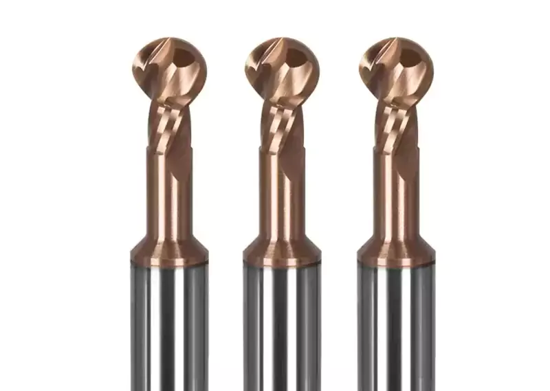
Undercuts in CNC machining refer to areas of a component or part that have recessed or indented features that are difficult to access or machine with standard cutting tools. Dealing with undercuts during the CNC machining process can be challenging and requires specialized techniques and tooling to achieve the desired shape.
To overcome undercuts, CNC machinists use various methods such as using angled cutting tools, employing multi-axis machining, utilizing Electrical Discharge Machining (EDM), or making additional setups or tool changes.
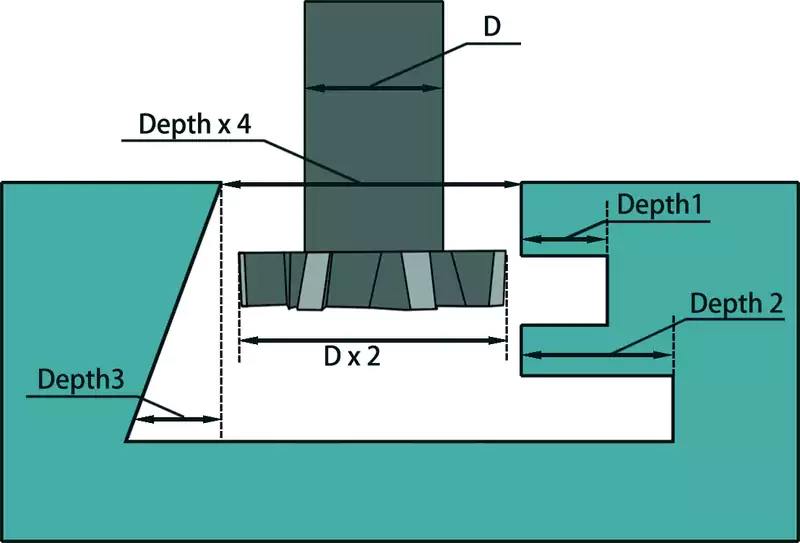
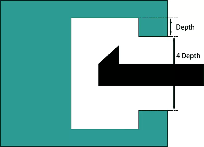
In CNC milling processes, a common way to handle undercuts is by using a slot cutter, a dovetail cutting tool, or a lollipop cutter. However, it’s generally recommended to avoid designing undercuts if possible, as they can increase lead time and cost. Standard tools have limitations on the cutting depth, typically with a ratio of 2:1 between the cutting diameter and the shaft diameter. Therefore, if the opening of a cavity is less than four times the depth of the undercut, machining tools will face difficulty in creating the undercut feature. For non-standard undercuts, CNC machine shops may need to create custom tools, which further increases both lead time and cost.
In CNC lathing processes, the most common approach to dealing with undercuts is using an internal grooving tool, also known as a slot cutter. It’s advised to keep the depth of the undercut less than 1/4 of the open hole diameter, for similar reasons as in milling undercuts.
To ensure a smooth and efficient manufacturing process, it is crucial to avoid designs with un-machinable undercuts. If an undercut is absolutely necessary, it is advisable to keep the depth of the undercut to a minimum. By following these design guidelines, you can optimize the manufacturability of your CNC machined parts while minimizing complexities and potential limitations associated with undercuts.
Avoiding Deep Holes in Machining
Deep holes, defined as those with a depth exceeding 10 times the diameter, present several challenges in machining processes. These challenges include tool runout, issues with “walking”, chip evacuation, and cooling.
Tool runout refers to the drill tip orbiting around the axis of rotation, which becomes more pronounced with longer drills and can lead to increased hole diameter.
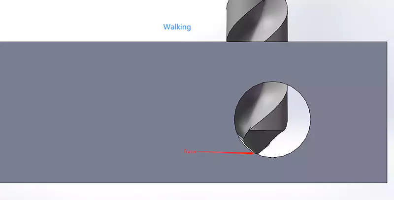
“Walking” occurs when the drill tip encounters a non-perpendicular surface, causing the drill to shift and potentially result in misaligned or angled holes. This can also occur with surfaces with an as-cast or rough-milled finish, potentially leading to drill breakage.
In deep holes, the chips produced during drilling tend to wrap around the drill flutes and build up, causing increased friction against the hole walls. This raises the temperature and can ultimately cause the drill to seize or break.
Cooling poses a challenge in deep hole drilling, as it becomes difficult to effectively deliver cutting fluid to the bottom of the hole. The resulting increase in drill tip temperature can damage the workpiece or even cause the drill to weld onto it.
The challenges of deep hole boring in CNC turning are similar, with the overhang length of the boring tool affecting its natural frequency and potentially triggering resonance and chatter marks on the parts. The long overhang can also lead to the bending of the tool and cause tapered holes, especially when dealing with hard-to-machine materials like stainless steel, titanium, and hard steel.
Avoid too Deep Cavities
In both deep-hole drilling and milling, the depth-to-width ratio plays a significant role in the challenges faced. Deep cavities require long overhang milling tools, which result in tool vibrations and slight bending, making it difficult to achieve high accuracy. Similarly, creating small features at the bottom of deep cavities presents challenges in meeting high tolerances.
As a general guideline, tool length-to-diameter ratios of 2xD to 5xD are typically manageable without significant issues. Ratios of 5xD to 10xD often require custom-made tools that can be expensive and challenging to achieve accuracy. For ratios exceeding 10xD, traditional tools and machines may not suffice, necessitating specialized tools and techniques that can be both costly and demanding.
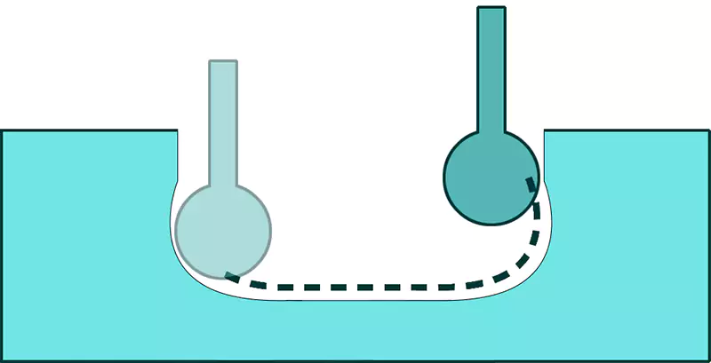
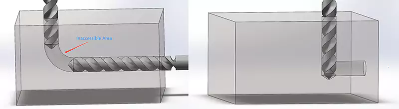
Avoid designing features that can not be accessed by tools
When creating designs, it is important to avoid incorporating features that cannot be reached by machining tools. As demonstrated in the left figure, the middle section of the design is inaccessible to tools, making it impossible to machine using a CNC milling machine. In contrast, the right figure showcases a design that is much more easily machinable. The key takeaway here is to always consider how tools will be utilized to bring the desired features to life.
Avoid multiple surface finish on a single-part
It is advisable to avoid incorporating multiple surface finish for a single part. We have encountered cases where aluminum parts required both passivation and anodization or even two-color anodization. While not impossible, achieving such requirements poses significant challenges. The second part of the surface treatment often requires manual masking, resulting in higher costs. Additionally, multiple surface treatments increase the likelihood of production failures. Therefore, it is recommended to minimize the need for multiple surface finish whenever possible.
Enhance Inside Corners by Adding a Radius
Enhance the functionality of sharp inside corners by adding a radius. These challenging corners are difficult for round-cutting tools to access. Here’s a closer look:
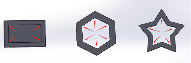
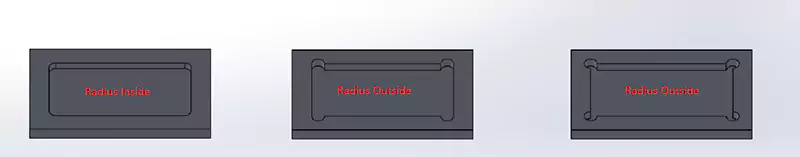
Since cutting tools require rotation to operate, achieving a sharp inside corner becomes impractical. In many cases, a simple solution is to incorporate a radius in the corner. This is typically a feasible option unless there are specific constraints preventing the use of a standard radius. Adding an internal corner radius is beneficial. Alternatively, if a radius on the inside is not suitable, consider applying it on the outside.
If a sharp corner is absolutely necessary, there are methods to address them, but they tend to be expensive. Here are a couple of approaches:
Broaching: This technique involves using a broaching machine or a rotary broaching tool on a CNC machine. However, these methods are costly and generally employed for larger production volumes. (Reference: YouTube video on broaching)
Wire EDM or Sinker EDM: EDM stands for Electrical Discharge Machining, which uses voltage to disintegrate material rather than cutting it with a traditional tool. Wire EDM employs a thin wire to cut the corner, resulting in a small radius equal to the wire’s diameter (plus a slight allowance for a spark gap). Sinker EDM, on the other hand, uses a solid block of material as an electrode. One drawback of this process is the rapid wear and replacement of the electrode. Additionally, Sinker EDM is a slow and costly process, especially when high precision is required.
In conclusion, it is important to note that all the methods for achieving sharp corners come at a considerable expense. Whenever possible, opt for adding a radius either inside or outside the corner to mitigate costs.
Avoiding Extremely Small Features
It is advisable to avoid incorporating extremely small features in CNC lathing and CNC milling processes. These machines typically operate with power consumption ranging from a few to a few dozen kilowatts. Attempting to create features that are 1mm or smaller in size is akin to embroidering with a hammer and chisel. While not entirely impossible, it is highly prone to errors.
There are several challenges associated with working on such minuscule features. Either the tool or the feature itself may not possess sufficient strength to withstand the forces exerted during the machining process. For instance, drilling a hole with a diameter of 0.5mm on a CNC milling machine is exceptionally difficult and requires utmost caution to prevent tool breakage. Handling such tiny features, be it holes smaller than 1mm or bosses smaller than 1mm, demands specialized tools, specific machines, and sometimes even exceptional skills. Consequently, the cost involved in accomplishing these tasks tends to be high.
Minimizing Machine Setups for Cost-Effective CNC Machining
The cost of CNC machining is directly influenced by the overall machining time, which comprises both machine setup time and actual machining time. The more setups required, the higher the production cost. This is particularly significant when dealing with small production volumes, as setup time becomes a major component of the total cost. Therefore, it is advisable to design parts that can be machined with as few machine setups as possible, ideally using just one setup.
One effective strategy is to concentrate multiple features in a single direction. By doing so, it becomes feasible to complete the machining process with only one setup. In contrast, designs that disperse features across different directions necessitate multiple setups, thus increasing costs. Consider the example illustrated below:
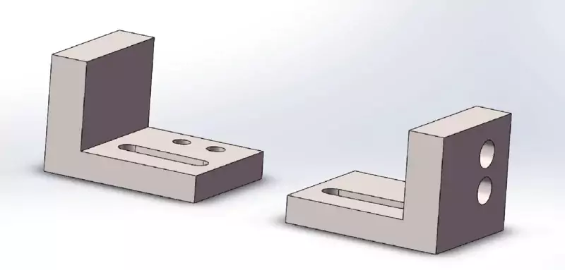
Designers can also explore the option of dividing a single part into two or more separate components and then connecting them using bolts or welding. This approach allows for easier machining and assembly, further reducing the number of setups required.
By minimizing machine setups through thoughtful design considerations, it is possible to achieve more cost-effective CNC machining while maintaining the desired functionality of the parts.
Tight tolerances can be costly in machining processes. Achieving precise tolerances requires machinists to work diligently and carefully. Trial and error may be necessary, taking into account tool wear and the careful selection of tools. Continuous monitoring is also essential to adjust machining setups when dimensions deviate. In short, tolerances come with a significant price tag, and tighter tolerances can be three times more expensive.
Tolerances are Expensive
Achieving tight tolerances in machining requires machinists to work with exceptional care and precision. It often involves trial and error to ensure the desired outcome. Machinists must also consider tool wear and carefully select appropriate tools for the job. Additionally, constant monitoring is necessary to adjust the machining setup when dimensions vary. In summary, achieving tight tolerances can be quite expensive, and having two tolerances can be three times more costly.
To mitigate these expenses, it is advisable to use tight tolerances only when absolutely necessary. Both geometric and dimensional tolerances come with a higher price tag, so it is essential to consider the cost implications when determining the required tolerances.
Considering Material Machinability
When making design decisions, factors such as strength, weight, and appearance requirements often dictate the choice of material. However, it is crucial to also consider the machinability of the material in order to minimize machining costs. For example, titanium is more difficult to machine compared to carbon steel, and SUS 304 poses greater challenges than SUS 303. Surprisingly, pure iron is even harder to machine than medium carbon steel. Materials with poor machinability can result in increased tool expenses and longer machining times. Moreover, certain features may be easily achievable on an aluminum part but impossible to produce on a SUS304 component.
As a tip, it is recommended to select materials that are easy to machine whenever the design requirements allow for it. By prioritizing materials with good machinability, it is possible to reduce machining costs and optimize the manufacturing process.
Use Standard Thread sizes
When designing components, it is important to consider available standard thread sizes. Many CNC machines provide the ability to create threads from scratch, but utilizing standardized thread dimensions can save time and resources. This helps to reduce machining costs and optimize production schedules. It is also better to talk with the machining service provider about what standards are favorable. Especially when making parts overseas. In countries like Germany, and China, metric system CNC threading tools are easy to find. In countries like the UK, Canada, or the United States, the imperial system and US systems are more popular.
The Continuous Development of CNC Machines and Tools
CNC machines and tools are constantly evolving, with new advancements and innovations emerging each year. As time goes on, some design tips may become outdated. This article focuses on strategies to lower costs and enhance design efficiency based on the general capabilities of CNC machining. CapableMachining provides free engineering consultation to assist you in improving your designs. If you have any questions about the design of CNC machining, please don’t hesitate to reach out to us.
Citation:
<1>
Published in 2015
On the Modern CNC Milling with a Compensation of Cutting Tools and Thin-Walled Workpiece Deflections
A. Polzer, K. Dufková, Premysl Pokorný
<2>
Czyzycki, J.; Twardowski, ˙ P.; Znojkiewicz, N. Analysis of the Displacement of Thin-Walled Workpiece Using a High-Speed C. Choosing the right material and corresponding tolerance for a job will help reduce expenses that come with extra processing time camera during Peripheral Milling of Aluminum Alloys. Materials 2021, 14, 4771. https://doi.org/10.3390/ ma14164771