Design and Simulation of CNC Turning Process for Parts
In the manufacturing process, the design and arrangement of the process are very important. Many times, to evaluate a company’s strength, you can look at the level of its process design.
What is process design?
Process design refers to rationally organizing the production process, formulating production process routes, determining the selection and design of production equipment, process equipment, tooling fixtures, etc., and formulating reasonable operating procedures and production plans based on the characteristics and requirements of the product. To achieve high-quality, high-efficiency products.
When designing the production process, you must first understand the product in depth, including its structure, function, performance requirements, etc. The best process route is determined through analysis and research of technology and process experience to ensure product quality and performance.
Secondly, after determining the process route, selecting and designing production equipment, process equipment, and tooling fixtures is necessary. According to the characteristics and process requirements of the product, appropriate types of equipment are selected, designed, and arranged. At the same time, according to the production quantity and other requirements, the quantity and configuration of the production equipment are determined to meet the production needs.
Then, formulate a reasonable operating process and production plan, convert the production process route into an actual operating process, and determine the operating methods, processing process parameters, process equipment, and use of tooling fixtures for each process. At the same time, a reasonable production plan is developed based on the production quantity and delivery date of the product to ensure that qualified products are delivered on time.
Finally, the production process design is optimized and improved. Based on the actual production situation, summarize and redesign, and make improvements and optimizations to address existing problems and deficiencies. By introducing new processes and technologies, we optimize process routes and improve production efficiency and product quality.
It can be seen that there are only a few reasons why process design is needed in manufacturing processing: improving production efficiency, ensuring product quality, reducing costs, and improving product design flexibility.
But if a brand-new product has never been processed in the factory, how to verify whether the process is reasonable?
A professional software, UG software, can be used here to simulate processing to confirm whether the process design is reasonable. Below we use a practical case to illustrate its process and working principle.
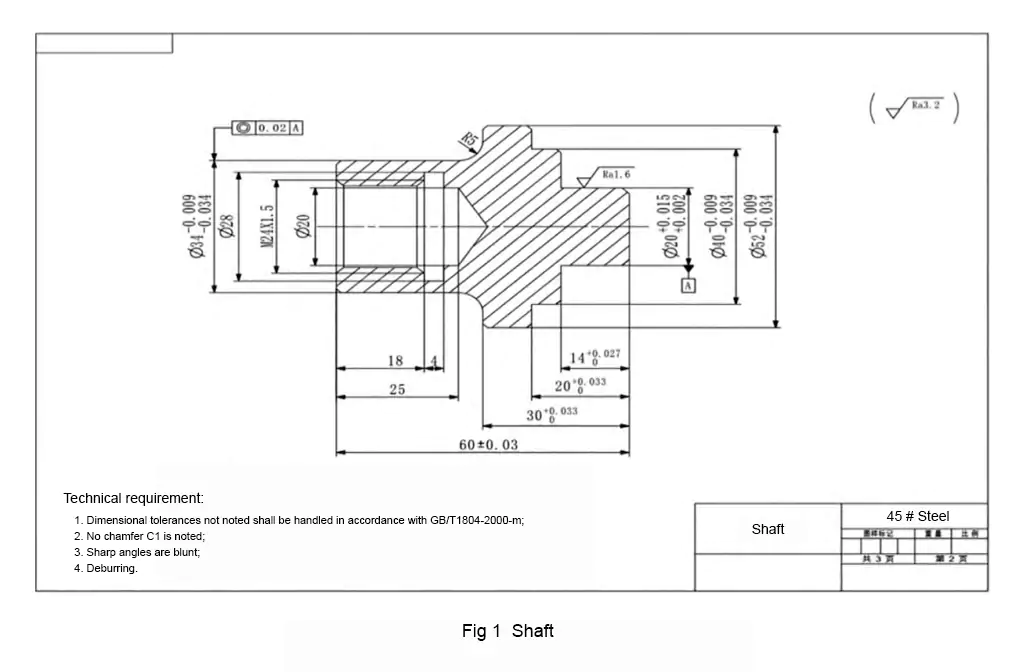
Take a typical transmission shaft as an example to discuss the CNC turning process design and simulation processing process, as shown in Figure 1.
CNC machining Process design
1. Overview of shaft parts
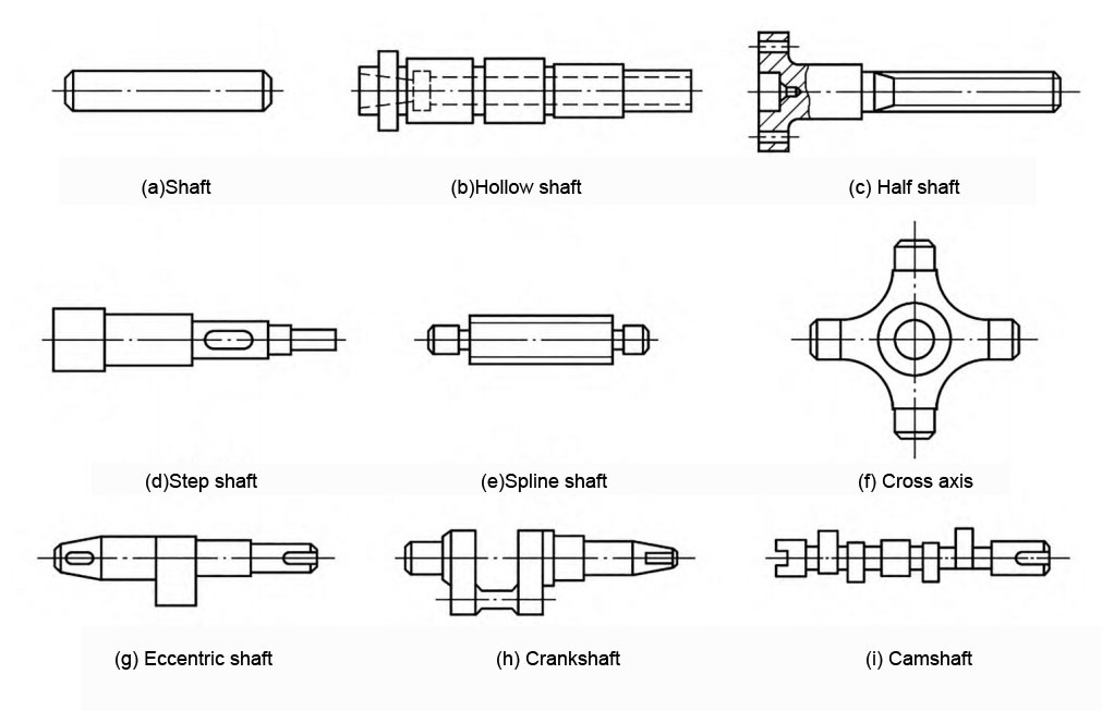
Shaft parts are generally installed and fixed inside the box, and cooperate with gears, bearings, etc. to form a whole. They are one of the important components in the reduction device. They have the function of transmitting power and torque and are typical rotary body parts. There are many types of shafts, which can be divided into smooth shafts, hollow shafts, half shafts, stepped shafts, splined shafts, cross shafts, eccentric shafts, crankshafts and camshafts, etc., as shown in Figure 2.
The surfaces that need to be machined on shaft parts mainly include end faces, step surfaces, internal and external cylindrical surfaces, threads, undercuts, etc. Since shaft parts are rotating bodies, attention must be paid to controlling the limit deviation and tolerance requirements when processing the outer cylindrical surface. ; When processing a slender shaft, attention must be paid to controlling its shape accuracy; due to the cooperation between the shaft, gears, and bearings, attention must be paid to ensuring its surface roughness and mutual position accuracy requirements when processing the inner cylindrical surface. Shaft parts generally use the outer cylindrical surface or the inner cylindrical surface as the positioning surface. The difficulty in processing is to ensure shape accuracy and prevent deformation.
There are many processing methods for shaft parts, and the processing process route needs to be selected according to the actual accuracy requirements of the part. The most typical process routes are blank preparation, heat treatment, center hole drilling, flat end face, rough machining of the outer surface, quenching and tempering, semi-finishing, Milling keyway, heat treatment, rough grinding, fine grinding.
2. Analysis of processing drawings
As shown in Figure 1, the transmission shaft has a step on the right end and an inner hole on the left end. It includes features such as outer cylindrical surface and arc surface, as well as internal threads, inner holes, etc., and requires many processing steps. The left end of this part has a φ34 outer circular surface (upper deviation -0.009mm, lower deviation -0.034mm) and has coaxiality requirements. The difficulty in processing the left end is internal thread processing. The right end is the outer circular surface of the step surface φ20mm (upper deviation +0.015mm, lower deviation +0.002mm) and the surface roughness value is Ra1.6, and the outer circular surface of φ40mm (upper deviation -0.009mm, lower deviation -0. 034 mm), the outer circular surface of φ52mm (upper deviation -0.009mm, lower deviation -0.034mm). From the above analysis, it can be seen that the dimensional accuracy of this part is high, the surface roughness at the right end diameter of 20mm is high, and the rest of the roughness value is Ra3.2, so CNC turning is used for processing.
3. Selection of blank and positioning datum
The commonly used material for shaft parts is 45 steel. Its strength, hardness, toughness, and wear resistance can be increased through heat treatment such as tempering and surface quenching. It is used for important shaft parts of medium complexity. The blanks of shaft parts include profiles, forgings, and steel castings.
According to the size requirements, structure, and shape characteristics of the transmission shaft parts drawing, combined with the existing equipment, the optional blank size is 65×φ55mm, and the material is 45 steel bars. The right end of the part is processed first, and the φ55mm outer circle of the bar is used as the rough datum positioning. Then the left end is processed by U-turn and clamping, and the φ52mm outer circle surface of the right end is used as the fine datum positioning.
4. Selection of fixtures and tools
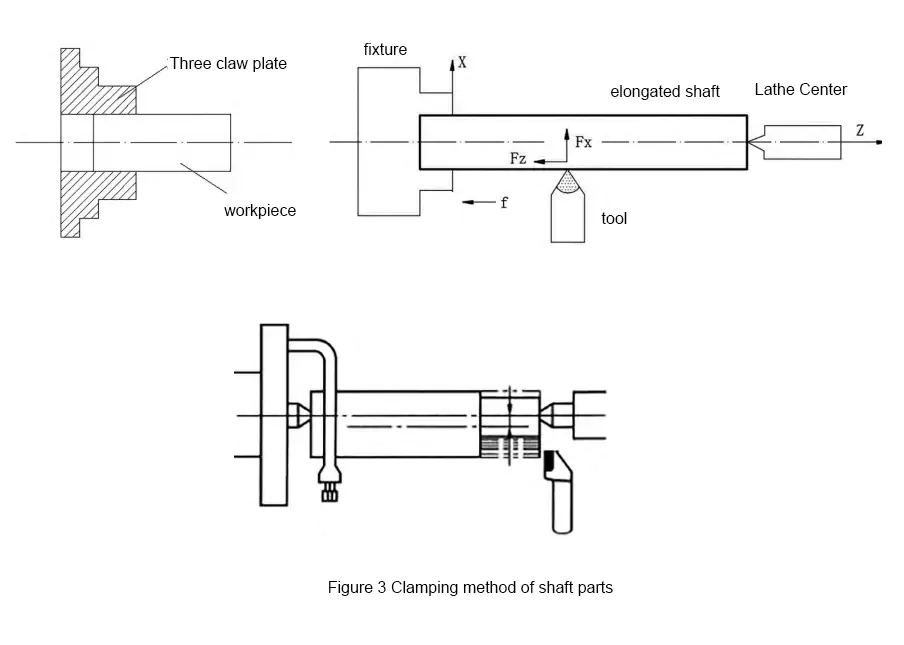
As shown in Figure 3, there are three ways to clamp shaft parts on CNC lathes: direct clamping on a three-jaw chuck, one-clamp and one-top clamping, and double-top-tip clamping.
Usually, shorter parts are clamped directly with a three-jaw chuck; parts that are longer or require multiple clampings to complete or parts that need to be ground after turning are clamped with double tips; the one-clamp and one-top clamping method is safe and It is reliable and can withstand large axial cutting forces. It is often used for semi-finishing and finishing of slender shafts with an aspect ratio greater than 15. According to the shape and structural characteristics of the part, the transmission shaft is clamped by a three-jaw chuck. To improve the efficiency of cutting processing, combined with the equipment conditions, choose machine-type turning tools: 1 350 external turning tool, 1 4mm external groove tool, 1 600 external thread tool, and 1 φ20mm drill bit.
5. Analysis of turning processing technology
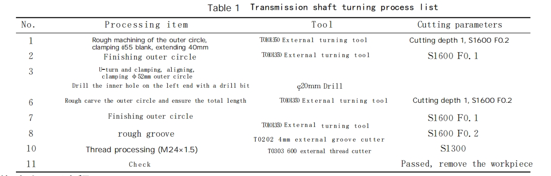
The transmission shaft parts are mainly composed of an outer circular surface, inner circular surface, hole, inner ring groove, and internal thread. There is an inner hole at the left end of the part and the radius of the thinnest part is 7mm. The dimensional accuracy of the inner hole is not high. The main difficulty is turning the internal thread and ensuring the dimensional accuracy of the φ34 outer surface. The outer cylindrical surface on the right end of the part is in the shape of a step, and the overall dimensional accuracy is required to be high. The difficulty is to ensure the surface roughness requirement of the outer circular surface of φ20mm. As shown in Table 1, it is the transmission shaft processing technology table.
Simulation Processing Process
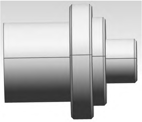
As shown in Figure 4, it is a three-dimensional model of the transmission shaft. To verify the correctness of the selected tools and formulated processing technology, facilitate continuous optimization of the processing process, and avoid accidents caused by direct processing on CNC machine tools, simulation software is usually used to simulate the processing process of parts in practice. This study uses UG NX8.5 simulation software to simulate and process the left-end outer cylindrical surface, right-end outer cylindrical surface, inner ring groove, and internal thread of the transmission shaft on the computer and generate a program. According to the particularity of the parts, the simulation is performed in the following order.
1. Simulation processing of the right end outer cylindrical surface
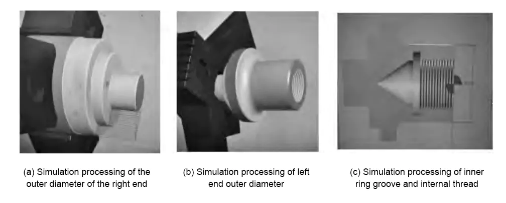
As can be seen from the parts diagram in Figure 1, the right end of the transmission shaft is composed of steps, chamfers, right-end surfaces, and outer cylindrical surfaces. Its processing characteristics are external contour processing and flat end surfaces. The simulation process is as follows: First, select the 35° cylindrical turning tool and set it as a T01 turning tool. First, perform the flat end face, and test the cylindrical and end face of the workpiece for tool setting. Secondly, set the workpiece coordinate system, taking the center point of the right end face of the part as the zero point, and using this as a reference to set the right side of the zero point as the positive direction, that is, the positive direction of the Z-axis; set the top of the zero point as the positive direction, that is, the positive direction of the X-axis. Third, perform simulation processing. After the settings are completed, simulation processing is performed. Figure 5(a) shows the part simulation processing results, and the right-end cylindrical processing program is generated, as shown in Table 2 and named O1.
2. Simulation processing of the inner hole and outer cylindrical surface at the left end
As can be seen from the parts diagram in Figure 1, the left end of the transmission shaft is mainly processed for the outer cylindrical surface, arc surface, chamfering, and end surface. After the outer circle processing of the right end of the part is completed, turn around and clamp the workpiece, leaving enough length, and then perform simulation processing of the left end. The simulation process is as follows: First, test-cut the outer circle and end face of the workpiece for tool setting. Here, No. T02 (grooving tool) and No. T03 (internal threading tool) is used for the toolset at the same time, and then-No. T01 outer turning tool is used to flatten the end surface, ensuring that The total length of the parts meets the drawing requirements.
Next, set the workpiece coordinate system, taking the center point of the left end face of the part as the zero point, and using this as a reference to set the right side of the zero point as the positive direction, that is, the positive direction of the Z axis; set the top of the zero point as the positive direction, that is, the positive direction of the X axis. Third, perform simulation processing. After the settings are completed, simulation processing is performed. Figure 5 (b) shows the part simulation processing results, and the left-end outer circle processing program is generated and named O2. Fourth, use a φ20 drill bit to complete the φ20×25 inner hole processing.
3. Simulation processing of inner ring groove
It can be seen from the parts diagram in Figure 1 that there is an inner ring groove with a diameter of φ28mm and a width of 4mm in the inner hole of the left end of the transmission shaft. The simulation process is as follows: First, according to the size of the inner groove and the part structure, select an internal grooving tool with a width of 4mm to complete the simulation processing of the inner ring groove of the φ28×4 hole. Secondly, select the appropriate speed and feed, and use No. T02 to perform simulation processing. Figure 5(c) shows the part simulation processing results, and the inner ring groove processing program is generated and named O3.
4. Simulation processing of internal thread at left end
As can be seen from the parts diagram in Figure 1, the internal thread at the left end of the transmission shaft is M24×1.5. Considering the hysteresis characteristics of the machine tool servo system, the lead-in length and overrun length should be considered when setting the thread processing length, so the thread processing length is equal to the lead-in length. The simulation process is as follows: use T03 No. 600 external thread cutter to perform simulation processing. The part simulation processing results are shown in Figure 5(c). The internal thread processing program is generated and named O4.
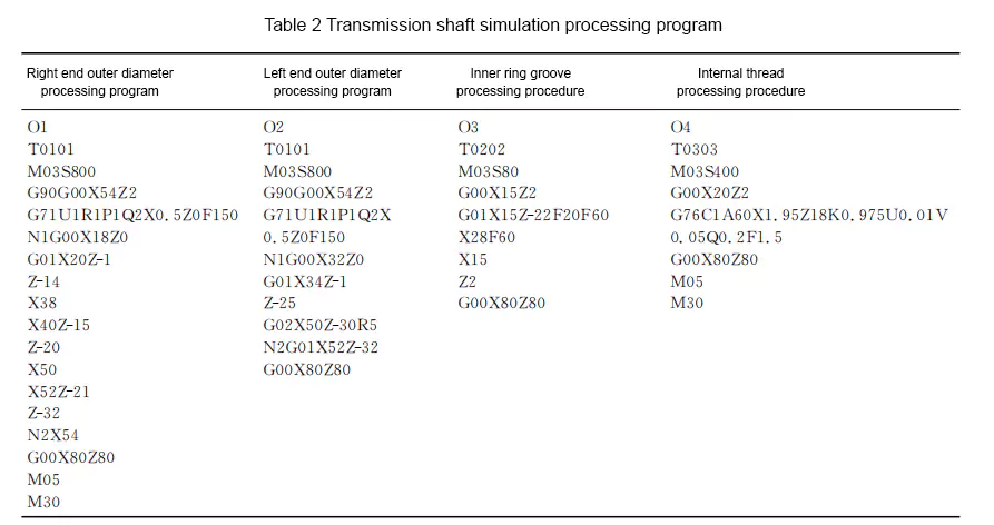
Through simulation processing, during the simulation processing process, we adjusted different cutting parameters for testing and found that the above process was compiled correctly, the tool angle and cutting amount parameter selection met the requirements, and the accuracy of the transmission shaft after simulated processing could meet the drawing parameter requirements. Therefore, the programs generated by each stage of simulated processing are summarized as follows after certain optimization, as shown in Table 2.
Conclusion
CNC turning processing includes turning outer circles, end faces, inner holes, grooving, thread turning, etc. It mainly processes rotary parts. When CNC turning the transmission shaft, it is necessary to carefully analyze the part drawings, comprehensively consider the matching of the parts and the processing situation, and prevent the occurrence of scraps. It is necessary to use simulation software to simulate processing and improve the efficiency of CNC turning.