Differences and connections between CNC machine tool origin, reference point, and workpiece zero
The application of CNC machine tools in the manufacturing industry is becoming more and more popular, at the same time with the growth of the service life of CNC equipment, CNC machine tool repair and maintenance of the task is also increasingly heavy. CNC machine tools in the scale and motor encoder are the most important measurement systems, if the replacement of the scale or encoder will need to reset the reference point of the machine tool; in addition, due to the collapse of the CNC system, data loss, etc. also need to reset the reference point of the machine tool.
In practice, due to the reference point and the origin of the machine partially overlapping it is easy to confuse them together, can not tell the difference and relation between the two, and some even call them the same point. Accurately understanding the concept of machine origin and reference point, and grasping the difference and connection between the two is conducive to our rapid troubleshooting and efficient solution to such problems in practice.
Machine origin and machine coordinate system
Machine tool origin, also known as the zero point of the machine tool, is the zero point of the machine tool coordinate system, the point at the beginning of the machine tool design has been established, it can be said that it is the machine tool dimensions of the design reference, its position is fixed and can not be moved. The machine control panel shows the machine tool axis coordinates of the position based on the machine coordinate system through the scale and other measurement systems.
Therefore, the origin of the machine is absolute and unique. Based on this the installation commissioning and maintenance of CNC machine tools are used in the machine tool coordinate system under the coordinate value rather than using the workpiece coordinate system under the coordinate value.
As shown in Figure 1, the machine coordinate system is generated by the design basis, therefore, it is neither visible nor easy to measure on the actual machine. The setup of the machine must be accurately established by the design drawings of the machine coordinate system, and for this reason, the introduction of the reference point, reference point is a specific fixed position point, which can be a tab, or a hole, which to the zero point of the machine tool is a clear distance and in practice can be measured to the point.
As shown in Fig. 2, it is not possible to find the zero point of the X-axis directly. For this purpose, the reference point of the X-axis can be found first, and with the position of the reference point, the position of the zero point can be obtained. After each axis of the machine tool has a reference point, you can find the zero point of each axis, and the zero point of each axis will inevitably converge together, which is the zero point of the machine tool.
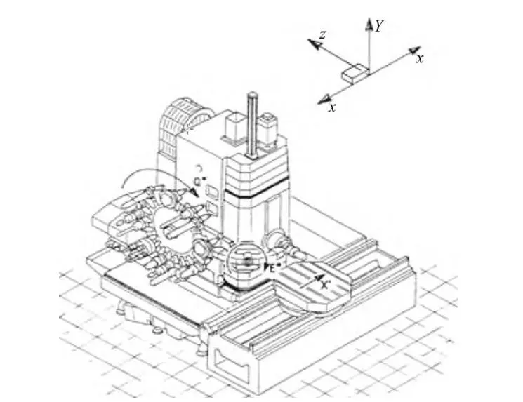
Figure 1 Example of a machine coordinate system
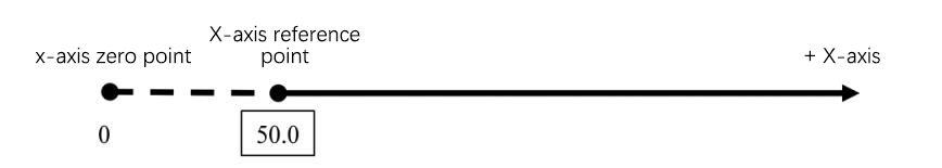
Fig. 2 Example of the relationship between the zero point of an axis and the reference point of the axis.
Concept of Reference Points and Role of Reference Points
1. The concept of reference point
The reference point of a CNC machine tool is a fixed position point used for detecting and controlling the movement of the machine tool. The position of the machine tool reference point is precisely adjusted by the machine tool manufacturer in each feed axis, and the coordinate value of the fixed position point has been recorded in the parameters of the CNC system.
The position of the machine’s reference point must be within the effective travel range of operation. In principle, there can be countless reference points, so the reference point of a certain axis may coincide with the machine’s origin, which is why some people think that the reference point and the origin are the same.
CNC machine tools need to reach zero point after power on, this is because the machine tool in the power failure, the loss of the coordinates of the position of the memory, so in the power supply, we must make the axes back to the machine tool to a fixed point, this fixed point is the machine tool reference point. Making the machine back to this fixed point of operation is called back to the reference point or back to zero operation.
2. CNC machine tools back to the role of the reference point
From the above, it can be seen that the reference point has an important influence on the coordinate position of each axis of the machine tool, and the role of the reference point is mainly reflected in the following two aspects:
(1) The system determines the origin position of the machine tool by returning the reference point, to correctly establish the coordinate system of the machine tool.
(2) Pitch error compensation and backlash compensation take effect, and soft limit travel protection takes effect.
Prerequisites for resetting the machine reference point
Generally speaking, there is no need to change or calibrate the reference point after the machine is installed and commissioned, but it is necessary in the following cases:
(1) when an axis of the scale or encoder is replaced, the a need to reset the reference point of the axis.
(2) When a large mechanical collision occurs, the reference point of the relevant axis needs to be detected and set.
(3) When the CNC system crashes or the system parameters are lost, it is necessary to reset the reference points of each axis.
1. Setting Methods for X, Y, and Z Axis Reference Points
The following describes how to set the reference points for the X, Y, and Z axes on a 5-axis horizontal machining center from GROB Machine Tools.
2. Setting the X-, and Y-axis reference points
Measuring tool: Toolholder, dial gauge, and short gauge rod Tolerance: 0.02 mm Procedure and points:
(1) Position the A-axis at 0° in manual mode.
(2) Record the coordinates of the reference hole on the label, for example, the coordinates of the reference hole on the label are X: 104.963 Y-81.024 Z287.878, as shown in Fig. 3.

Figure 3 coordinate value of the reference hole
Here the reference hole is a fixed position point, using the reference hole as a reference point for the establishment of the machine tool coordinate system, X, and Y coordinates of the center of the reference hole in the machine tool coordinate system from the zero point of the size; Z coordinates of the end face of the reference hole in the machine tool coordinate system from the zero point of the Z-axis of the size.
(3) In manual mode, use the handwheel to move the X, Y axes to the vicinity of the reference hole position, extend the spindle, mount the tool holder on the spindle, and then suck the dial gauge and the gauge rod onto the tool holder. Move the Z-axis and set the meter needle on the inner wall of the reference hole, preload about 0.2 mm, and set the meter to zero at the X0 position as shown in Fig. 4.
(4) Rotate the spindle 180° and stop the meter needle at the X1 position. Observe the swing direction of the meter needle, for example, if the meter reads +0.3 at the X1 position, move the X-axis in increments so that the meter needle rotates in the opposite direction and stops at +0.15, then rotate the spindle so that the meter needle stops at X0 position to see if the meter needle is still at +0.15. If not, move the X-axis again until the meter value is the same in both the left and right directions. If not, move the X-axis again, until the percentage meter value is the same or zero in both directions.
Move the Y-axis in the same way until the needle is the same or zero in both directions. At this time, the center of the spindle and the center of the reference hole are in the same line, which means that at this time the control panel on the X, and Y coordinates should theoretically be the same as the reference hole coordinates.
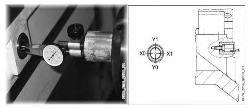
Fig. 4 Measurement of the center of the reference hole using a percentage meter
(5) Check whether the X, and Y axis coordinate values on the panel display are out of tolerance compared with the specified values on the label.
(6) If the difference is excessive, for example, the X-axis coordinate is X108.029 and the Y-axis coordinate is -135.1, which is far beyond the tolerance, it is necessary to reset the reference point of the X, and Y-axis. Press ” Main Menu→Commissioning→Machine Data→User View” on the control panel to find the interface of motor encoder parameters of X, Y-axis as in Fig. 5, find the parameter MD34100 under X-axis, input the specified coordinate value of X-axis of the center of the reference hole 104.963, and then change the parameter of MD34210 from 2 to 1, and then press ” Machine Tool” to change the parameter from 2 to 1. Then change the parameter of MD34210 from 2 to 1, and press “Machine Data Valid” → “Reset”, then rotate the multiplication knob of the machine to 0 and press “Machine → JOG → Ref point → +”. Then press “Machine → JOG → Ref point → +”, and you can see the coordinate value of the X-axis changed from X108.029 to 104.963. Returning to the interface of the motor encoder parameter, the parameter of MD34210 will be changed from 1 to 2 automatically, indicating that the calibration is successful.
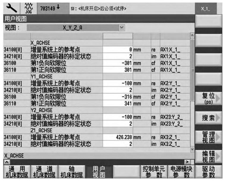
Figure 5 Axis Reference Point Parameter Screen
3. Y-axis Calibration
For the calibration of the Y-axis, the same operation is performed, note that the Y-axis coordinate value on the label must be input into the system parameter instead of inputting the current coordinate value of the Y-axis, the current coordinate value of the X-axis and the Y-axis is only for judging the over-abundance or non-over-abundance.
The X and Y axes should not be moved during the calibration process after the center of the reference hole is found, otherwise, it will cause a serious error and the whole operation will need to be done again.
4. Z-axis zero point detection and calibration
Measuring instrument: Standard block (100 mm) Tolerance:0.02
Operation steps and points:
(1) Position the A-axis at zero degrees in manual mode and record the Z-axis coordinates on the label, as shown in Fig. 3 Z: 287.878.
(2) Stop the spindle near the X and Y coordinates of the center of the reference hole.
(3) Move the Z-axis out of the spindle, in the spindle end face close to the end face of the reference hole with the amount of block to measure the gap between the two, until the 100 mm block in the spindle end face and the end face of the reference hole between the tightness can be appropriate, that is, after the release of the block will not fall, and at the same time can be used to take out the block. As shown in Figure 6.
(4) Compare the current coordinate value of the Z-axis on the panel with the coordinate value on the label, and judge whether the result is too poor.
(5) If there is over difference, then it is necessary to modify the parameters of the Z-axis motor encoder in the same way as above.
Note: When inputting the Z-axis parameter, it is not the value on the label, but the value of 100 of the size of the block, i.e., it is not 287.878, but 287.878+100=387.878. At the same time, the Z-axis position can not be moved again until the whole calibration process is finished.
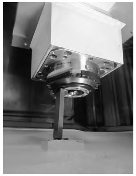
Fig. 6 Setting the Z-axis reference point
Principle of machine origin setting
Because it is not easy to find the position of X0 and Y0 directly, this sets an easy-to-find reference position (i.e., the position of the reference hole), the position of the reference point to the zero point of the position of the dimensions of the accurate measurement of the good and make a good record for future use (i.e., XYZ-axis coordinates), then in the future need to reset the position of the X0, Y0 only need to find the position of the reference point and then move from this position to the above measurements. Then, when you need to reset the position of X0 and Y0 in the future, you only need to find the position of the reference point first and then move the distance of the above measurements from this position. In practice, it is not necessary to move the above distance, but only need to record the distance from the zero point to the reference point in the system parameters.
Workpiece Zero and Workpiece Coordinate System
The zero point of the workpiece is also called the program zero point, which is defined by the CNC programmer according to the characteristics of the workpiece to facilitate the preparation of the tool path trajectory and the reference point. The coordinate system where the zero point of the workpiece is located is called the workpiece coordinate system, the workpiece coordinate system depends on the workpiece while the direction of the axes of the workpiece coordinate system must be consistent with the direction of the axes of the machine coordinate system.
Usually, one or more workpiece coordinate systems can be defined on a workpiece, and special G codes are used to represent different workpiece coordinate systems, such as G54, G55, G56, etc. As shown in Figure 7, the workpiece coordinate system is dependent on the workpiece and the direction of each axis of the workpiece coordinate system must be consistent with the direction of each axis of the machine coordinate system. As shown in Figure 7, the workpiece coordinate system is established by the machine operator using tools such as cutters, ruby probes, or edge finders to measure elements such as faces or holes in the workpiece.
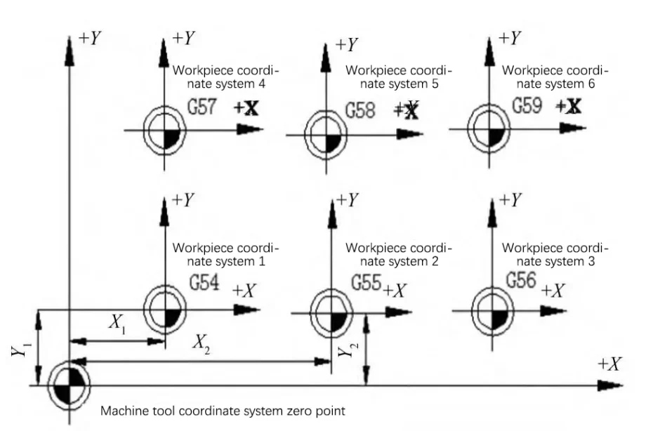
Figure 7 Machine and Workpiece Coordinate Systems
Difference and relationship between machine coordinate system and workpiece coordinate system
Machine tool coordinate system and workpiece coordinate system is often used in practical work of the two coordinate systems, there are obvious differences between the two and have a close relationship.
1. Main differences
(1) different concepts
As mentioned earlier, the machine tool coordinate system is the machine tool design basis, its position is fixed and can not be moved. Machine tool coordinate system has only one absolute and uniqueness. The Workpiece coordinate system is based on the characteristics of the workpiece by the programmer according to the programming needs and free definition, there can be more than one, and can be changed or canceled.
(2) Different roles
The machine coordinate system is for the design of machine tools, machine tool motion control, and generated. The Workpiece coordinate system is to facilitate the production of CNC programming.
(3) The establishment of different methods
The machine coordinate system is machine tool adjustment or maintenance personnel by setting the reference point of each axis and establishing. The Workpiece coordinate system is the machine operator through the tool or other tools to probe the workpiece and establish.
2. Relation
(1) The direction of each axis of the workpiece coordinate system must be consistent with the direction of each axis of the machine coordinate system. Both the workpiece coordinate system and the machine coordinate system are Cartesian Cartesian coordinate systems established according to the right-hand rule, so the names and positive and negative directions of the axes must be consistent.
(2) The machine tool coordinate system is the basis of the workpiece coordinate system, and the zero position of the workpiece coordinate system is a relative position point under the machine tool coordinate system through the principle of coordinate offset transformation.
Conclude
In summary, the origin is the zero point of the machine coordinate system, the machine coordinate system is established by setting the reference point of each axis of the machine tool, its role is to detect and control the movement of the machine tool, with the absolute, stability and uniqueness; zero point of the workpiece is the zero point of the workpiece coordinate system, it is because of the need for programming and the establishment of the reference point, which can be more than one and can be modified.