How to machining thin-walled parts?
Thin-walled parts are widely used in aerospace, national defense science and technology, nuclear power equipment, automobile manufacturing, and other fields because of their lightweight and compact structure, such as the overall spacer frame, the overall wing ribs, the overall wall plate and the turbine blades of the aero-engine and other non-general-purpose thin-walled parts, whose machining is mostly based on the milling process.
With the continuous development of manufacturing technology to promote the thin-walled parts machining efficiency and machining accuracy continue to improve. Due to the high removal rate of thin-walled parts processing, the molding of the workpiece stiffness is reduced, in the milling process by the milling force workpiece is prone to large processing deformation, in the knife after the deformation will occur elastic recovery, and then the phenomenon of knife, so that the actual milling width is not equal to the nominal value, resulting in a reduction in machining accuracy, and even processing quality is difficult to ensure.
The deformation of thin-walled parts in the machining process is an important factor that directly affects the machining accuracy, machining quality, and productivity of the workpiece.
Therefore, the study of predicting and controlling the machining deformation of thin-walled parts is of great practical significance.
Workpiece Classification and Processing Characteristics
Thin-walled parts usually refer to the wall thickness and axial or radial size ratio greater than 1/10 of the parts, due to the many thin-walled parts belonging to non-standardized parts, in the definition of thin-walled parts, the ratio of its wall thickness and length will vary, but thin-walled parts have a low relative mass, high specific strength, structural complexity and rigidity and other characteristics of the weak.
1. Classification of thin-walled parts
Thin-walled parts can be divided into shape, material, and structure. The shape can be divided into circular, shell, and flat plate; the material can be divided into an aluminum alloy, titanium alloy, and composite materials, etc.; according to the structure can be divided into the frame class, the whole wall plate, beams, and curved surfaces, because of its structure, thin-walled parts have different characteristics.
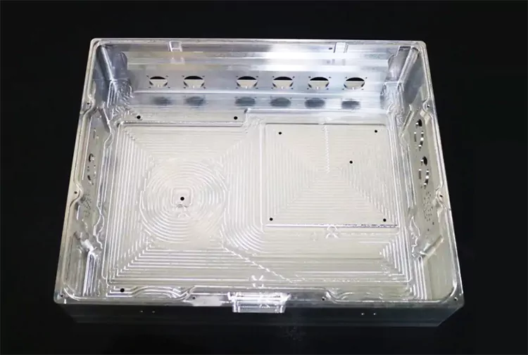
(1) frame class parts. As a typical part of the aerospace vehicle fuselage structure, is the main stress component of the transverse structure of the fuselage, but also constitutes and ensures the radial attitude of the fuselage of the main structural components. As shown in Figure 1, its structure consists of the outer and inner frame surfaces of the workpiece, and the web of the reinforcement structure. In short, the frame structure is composed of the web, and its wall thickness ranges from 1.5 to 2.0mm. The connection parts of the frame parts are generally combined with grooves or combined with the plane, but the thickness of the web in the same frame parts is not the same.
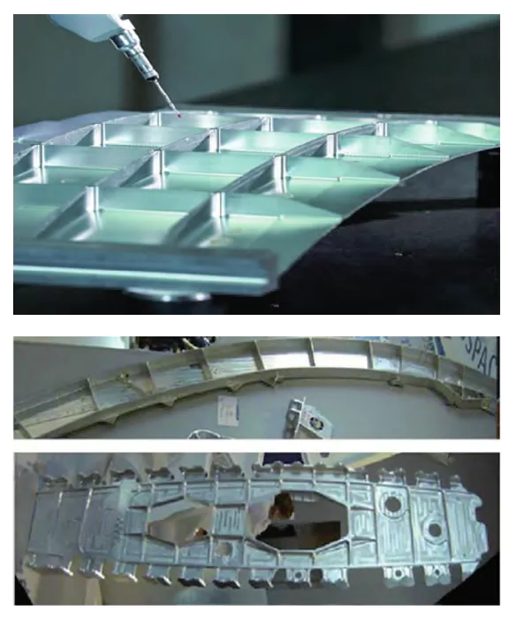
Fig.1 Thin-walled frame pats
(2) Integral class wall plate. By the rib, skin tab edge strip, and other structural components, in aerospace load-bearing thin-walled parts are more applications, such as wings, tails fuselage longitudinal structure, etc., as shown in Figure 2. Integral wall plate and the traditional riveted or bolted joints compared the advantages of reducing the number of parts, reducing the assembly process, improve the smoothness of the surface and the fatigue resistance of the parts; the disadvantage is that the overall size of the cross-section with a larger size ratio, the relative rigidity of the poorer, prone to machining deformation.
(3) beam parts. With the continuous improvement of aerospace performance, beam parts not only require high strength and stiffness but also to reduce quality, to meet its performance requirements, the frame is more complex, according to the cross-section shape, can be divided into I-shaped, U-shaped, and even more complex shaped cross-section, etc., such as shown in Figure 3 for a typical beam parts.
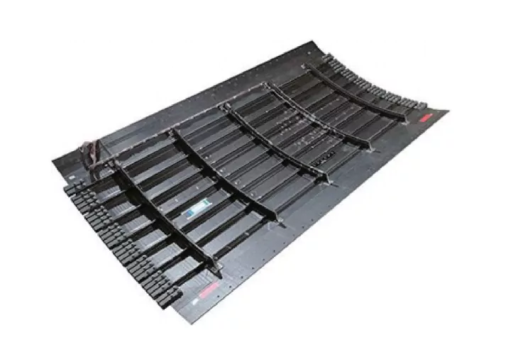
Fig.2 Integral panel pats
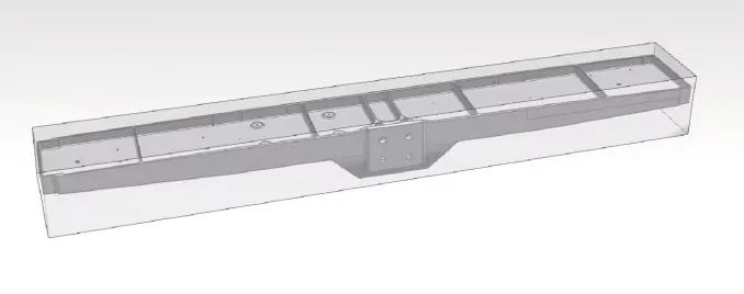
Fig.3 beam parts
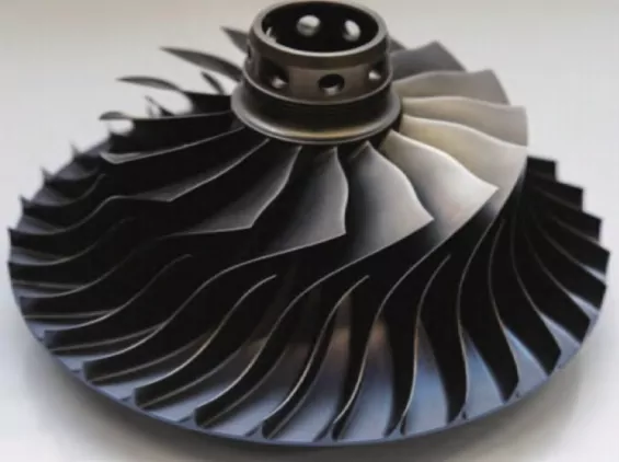
(4) Complex surface parts. This type of part has the shape, structure, and complexity of the machining accuracy requirements of high characteristics, with the continuous development of aerospace vehicles, curved surface parts are more and more, and the most representative such as impellers, and blades, are an important part of the aero-engine, such as shown in Figure 4.
(5) Thin-walled shaft parts are made of too thin materials and are very sensitive to temperature changes and external impacts.
2. Machining characteristics
Due to the specificity of the structure and shape of the thin-walled parts, it determines the uniqueness of its processing characteristics, mainly the following three points:
(1) STRUCTURAL: in the milling process, with the continuous thinning of the wall thickness of the parts, the relative stiffness is getting lower and lower, prone to cutting vibration and deformation, and can not guarantee the stability of processing and processing quality.
(2) FUNCTIONAL: the processing of thin-walled parts not only ensures high machining accuracy but also requires a high degree of assembly accuracy in the joints and other parts to ensure that the parts have a reasonable assembly performance to meet the requirements of use.
(3) MATERIAL: thin-walled parts are mostly high-strength aluminum alloys, titanium alloys, or high-temperature alloys, whether it is easy-to-cut materials such as aluminum alloys, or titanium alloys and other hard-to-cut materials, deformation problems are more prominent.
Therefore, the control of processing deformation has become a key issue, the conventional machining process can not guarantee the accuracy of the processing, generally using manual or mechanical grinding to achieve the accuracy requirements.
3. Adverse effects of machining deformation
Thin-walled parts usually have a complex structure, large volume, and other characteristics, and machining accuracy requirements, but in the manufacturing process, due to the low rigidity, the metal removal rate is large, in the cutting force under the action of the workpiece to produce large deformation, the elastic deformation recovery after machining, resulting in part of the material can not be removed, and need to be manually polished so that the processing efficiency is greatly reduced;
In the process of machining, the workpiece cross-section size and contour size difference is large, the rigidity is getting lower and lower, not only occurring in the overall deformation of the bending and twisting, but also prone to causing cutting vibration, resulting in a decline in machining accuracy and surface quality, seriously affecting the performance of its use, and even cause the parts to be scrapped.
Therefore, to process the parts to meet the requirements of the thin-walled parts it is necessary to predict and control the amount of deformation accurately.
Deformation Factors
Thin-walled parts of large size, complex structure, low stiffness, material removal rate, etc., the above characteristics are not conducive to milling, after a series of complex processes, it is difficult to ensure that the deformation does not occur.
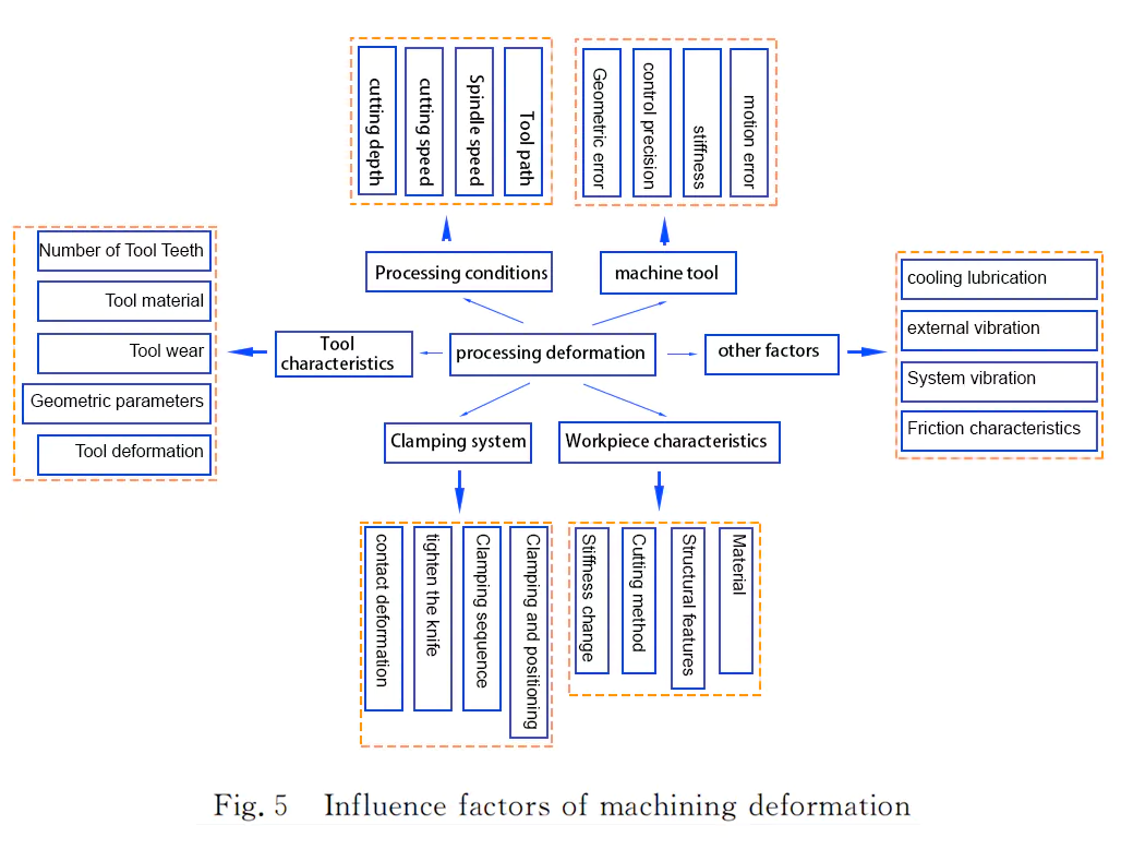
There are many factors affecting the processing deformation of thin-walled parts, therefore, the processing deformation factors are summarized, as shown in Figure 5, which has a greater impact on the processing deformation of thin-walled parts of the cutting force and cutting heat, workpiece material properties, clamping conditions, residual stress and tool path 5 factors.
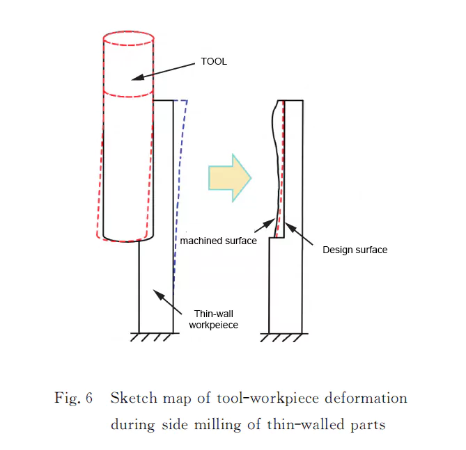
(1) Cutting force and cutting heat: in the milling process, due to the thin-walled parts of poor rigidity, milling force generated by the deformation of the workpiece extrusion deformation, rebound deformation, and tool deformation of the composition of the 2 aspects, as shown in Figure 6, resulting in the deformation of the trend is difficult to predict, and due to the deformation of the chips, chips and the front face and the back of the cutter face and the surface of the processed surface of friction between the surface of the workpiece processed with the sub-surface of the uneven distribution of temperature The inner layer of metal hinders the surface layer volume expansion tendency, this hindrance makes the surface layer of the parts to produce thermal stress, under the action of cutting force and cutting heat, the stress distribution of the workpiece has an impact, aggravating the deformation of the parts, making it difficult to ensure the machining accuracy.
(2) Workpiece material characteristics: thin-walled workpiece materials are generally aluminum alloy, titanium alloy, or high-temperature alloys, due to the small modulus of elasticity of the material, the specific strength of the material is very easy to rebound in the processing process, resulting in deformation of the parts. The same material, with the increase in part size, rigidity becomes poor, as well as their structural asymmetry will lead to greater processing deformation of the parts.
(3) Clamping conditions: the fixture is the parts and machine tool connection bridge, the role of the fixture is to locate and clamp the workpiece, for thin-walled parts, because of its thin wall, under the action of the clamping force, the workpiece undergoes the corresponding elastic deformation, which affects the shape of the surface of the workpiece and dimensional accuracy. In the cutting process, the clamping force and cutting force may interact, so that the initial residual stress and processing residual stress redistribution, resulting in thin-walled parts deformation.
(4) Residual stress: residual stress includes initial residual stress and processing residual stress 2 categories. Initial residual stress refers to the blank in the manufacturing process by external forces or uneven temperature field, resulting in uneven elastic-plastic deformation of the material. Processing residual stress in the machining process exists in the processing surface of the residual stress. Due to the cutting force and cutting heat, breaking the initial residual stress equilibrium state, the workpiece through the deformation of the internal parts of the stress reaches equilibrium again.
(5) Tool path: Different tool paths will lead to the original residual stresses in the workpiece in a different order of release, resulting in different processing deformation. With the machining process, the material is gradually removed, the workpiece gets thinner and thinner, and the stiffness also gets smaller and smaller, under the action of cutting force and cutting heat, resulting in machining residual stress. Due to different paths, the original residual stresses and processing residual stresses of different coupling order and effect, under the joint action of these complex factors, will lead to different deformation of the workpiece.
In summary, it can be seen that in the milling process of thin-walled parts, due to the low stiffness of thin-walled parts, the milling force is prone to elastic deformation and the emergence of the phenomenon of the knife, resulting in friction between the tool face and the machined surface, which not only affects the accuracy and quality of the machined surface but also reduces the life of the tool. With the continuous removal of the material, the workpiece stiffness decreases, the release of residual stresses and the re-establishment of equilibrium, different processing conditions, and other factors, will have a great impact on the final deformation of the workpiece. Therefore, it is important to analyze the factors affecting the machining deformation of thin-walled parts for the prediction and control of machining deformation.
Deformation control
To reduce and control the deformation of thin-walled parts machining, mainly including machining process optimization, auxiliary support technology, high-speed cutting technology, and CNC compensation technology.
1. Process optimization
The research on optimizing the deformation of thin-walled parts for the machining process is mainly carried out from the aspects of clamping layout, tool path, and cutting parameter optimization.
1.1 Optimize the clamping layout
Because of the low rigidity of the thin-walled parts themselves, the process of machining by the clamping force of the fixture will affect the shape of the workpiece to change accordingly. If the clamping support point is not selected properly, resulting in additional stress, the thin-walled parts of the obvious deformation;
In the milling process, milling force and clamping force will have a certain coupling effect, so that the original residual stress and processing after the new residual stress to achieve equilibrium will be redistributed, resulting in thin-walled parts deformation. The influence of the clamping system on the machining accuracy of thin-walled parts has received serious attention.
How to optimize the clamping layout?
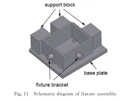
1.1.1 Using the FEM (Finite element method) method to establish the improved overall fixture system model, as shown in Figure 11, the improved fixture can significantly reduce the deformation of the frame-type thin-walled parts.
1.1.2 Dynamically changing the clamping force during the machining process can appropriately reduce the machining deformation.
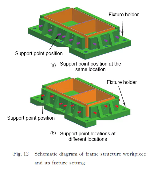
1.1.3 Thin-walled multi-frame parts, based on the Lagrange method to establish the fixture, shown in Figure 12. Reducing the machining deformation of the shape of the volume has a significant effect.
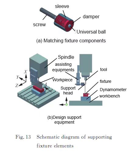
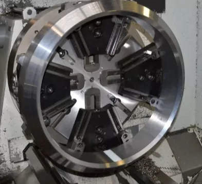
1.1.4 The method of adding a supporting fixture element to the backside of the workpiece contact area to control workpiece deformation is shown in Fig. 13, where the fixture element moves at the same speed as the milling cutter during the milling process.
1.1.5 Adopt different clamping programs, adjust the number of clamping elements and the clamping sequence to get the optimal clamping program, and improve the machining accuracy of thin-walled parts.
1.1.6 Adopt multi-point flexible tooling layout.
In the process of thin-walled parts machining, a reasonable clamping layout improves the machining deformation to a certain extent. Rigid clamping mainly relies on friction to make the workpiece positioning, because the workpiece and the clamping system material are fixed, the coefficient of friction between them is relatively certain, so the need for sufficient friction, is necessary to increase the clamping force, which will cause deformation of the workpiece;
1.1.7 Use magnetorheological fluid technology to add special flexible materials. When there is a magnetic field, the material will instantly transform from liquid to solid to support the material. This method can be used for thin-walled parts with extremely complex shapes and small sizes, but the cost is high , it is necessary to purchase special equipment and materials for processing.
1.1.8 Gypsum filling thin-walled parts is a common manufacturing process. Its principle is to use gypsum to fill the internal gaps of thin-walled parts to increase its strength and stability. The biggest advantage is that it is cheap. The disadvantage is that the volume of gypsum expands slightly after hardening (the expansion rate is about 1%). This method is not suitable if high-accuracy requirements are required.

1.1.9 For thin-walled flat parts, the following methods are currently commonly used in production:
- AB glue is simple, reliable, and cheap, but it is troublesome to remove the glue and the adsorption force is unstable.
- Vacuum Pads eliminate the trouble of removing glue, have strong adsorption power, and is reliable.
- Frozen suckers can solve the trouble of removing glue and have strong adsorption power, but they are slightly more expensive.
- Electromagnet sucker
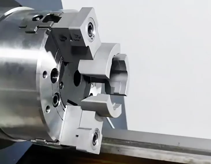
1.1.10 For shaft workpieces, the common methods currently used in production are:
- Special clamping external tooling: swing claw, etc.
- Spring mandrel clamp: it uses elastic deformation characteristics to automatically clamp the workpiece from the inside.
- Internal expansion chuck
- floating jaw
1.1.11 Soft jaw clamping
- A special way of clamping small thin-walled parts.
1.1.11 Flexible-fixture
1.1.13 other special fixture
In contrast to the use of flexible clamping, more arrangement of support points improves the utilization rate of the clamping force and can reduce the maximum clamping force, thereby reducing the deformation of thin-walled parts.
1.2 Optimize tool path
Tool path refers to the tool from the start of the movement of the tool point, to the end of the machining program through the path, by the cutting path and non-cutting air travel 2 parts. Toolpath deformation of the workpiece is indirectly affected, rather than directly related, mainly including two aspects:
First, the residual stress on the deformation: due to the different machining paths, the residual stress in the workpiece releases the order of differences, resulting in the deformation of the workpiece is not the same.
The second is the effect of workpiece rigidity on deformation: with the continuous removal of material, the workpiece rigidity is gradually reduced, and different machining paths will have an impact on the overall rigidity of the workpiece, resulting in different deformation results. Toolpath optimization can solve the residual stress deformation and elastic deformation of the workpiece.
How to optimize the tool path?
1.2.1 Based on the automatic measuring system with a trigger probe, the machining deformation of the blade is measured online in real-time, and a tool deviation path compensation model is established to form an adaptive thin-walled side milling machining method, which is experimentally verified to be able to reduce the deformation of the blade and improve its machining accuracy.
1.2.2 The minimum area criterion is adopted to fit the machined surface to the sampling points, and the optimized positioning of the tool trajectory is realized. Based on the differential nature of the distance function, quantitatively describing the changes of the machining error under the adjustment of the tool trajectory, the tool path optimization problem of compensating the machining deformation error is reduced to a mixed-integer linear programming problem, and then the mixed-integer linear programming problem is solved by using the branching and bounding method.
Finally, the validity of this error compensation model and algorithm is verified by comparing the prediction before and after compensation with the five-axis milling blade test.
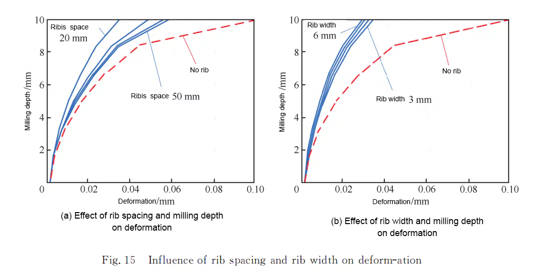
1.2.3 Based on the finite element method, a simulation model of the milling process of thin-walled parts is established, which is mainly used to study the influence of the rib structure on the machining deformation of thin-walled parts. As shown in Fig. 14, the machining process schematic from the blank to the workpiece, because the maximum deformation increases gradually as the thickness of the workpiece decreases in the machining process, in semi-finish machining, the rib structure is left, the rib spacing has 20, 30, 40 and 50 mm, and the width of the ribs has 3, 4, 5 and 6 mm, which is analyzed by simulation:
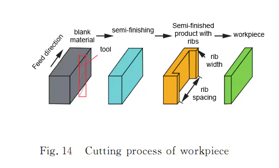
As shown in Fig. 15(a), the deformation increases significantly with the increase of rib spacing; as shown in Fig. 15(b), the increase of rib width has little effect on the deformation.
At present on the tool path and machining sequence the a need to do professional research, most of the current research is for single-frame parts or multi-frame thin-walled parts, through the different order of the tool, compared with the deformation of the workpiece after machining, to derive the minimum amount of deformation of the tool path, which can be used to provide a certain degree of significance to guide the actual machining.
1.3 Optimization of machining parameters
Milling speed, feed, milling width, and milling depth are the most basic cutting parameters in milling, these parameters are often based on machining experience or cutting manual, but these parameters may not be suitable for complex surfaces of thin-walled parts.
Because the thin-walled parts machining deformation increases with the material removal rate increases, the pursuit of a higher material removal rate, but do not want to thin-walled parts machining process occurs during the greater elastic deformation. The optimization of machining parameters can be appropriate to reduce the cutting force load and reduce the thin-walled parts of the elastic processing deformation.
How to do parameter optimization?
1.3.1 Based on the orthogonal test method to get the important parameters affecting the thin-walled parts machining deformation and the combination of machining parameters to minimize the machining deformation.
1.3.2 Study the influence of different finishing milling stages and milling depths on the machining deformation of thin-walled parts.
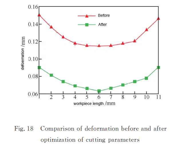
1.3.3 Simultaneous optimization algorithm based on finite element method and genetic algorithm.
As shown in Fig. 18, the optimized milling parameters can greatly reduce the deformation of thin-walled parts by comparing the simulation results.
1.3.4 Finite element orthogonal advantage analysis method, analyze the milling speed, milling depth, milling width, and feed per tooth on the milling deformation of the degree of influence, and then reduce the deformation of thin-walled parts in the process of machining as the objective function, to get the optimal combination of milling parameters.
Through the thin-walled frame parts for verification and the use of orthogonal advantage analysis of the optimized milling parameter combinations, the maximum deformation is significantly reduced.
1.3.5 Static simulation, the maximum deformation of different milling parameters as a sample, through the genetic algorithm for milling parameter optimization, simulation, and experimental comparison, the optimized milling parameters not only reduce the maximum deformation, to a certain extent, but also improve the production efficiency, and have a guiding significance to the actual processing.
1.3.6 According to the working condition mapping and thin shell stress fitting residual stress deformation simulation prediction method, the use of a support vector machine to establish the residual stress response prediction model, and then use the genetic algorithm to optimize the milling parameters, with the residual stress deformation as the constraints, the maximum machining efficiency as the goal of optimization of the feed rate, cutting speed and depth of cut, the optimization of the milling width and the other one-design variables. When the value of milling width and one other design variable is taken as a fixed value, the effect on residual stress deformation is investigated when the cutting efficiency is increased by the other two design variables, as shown in Fig. 19.
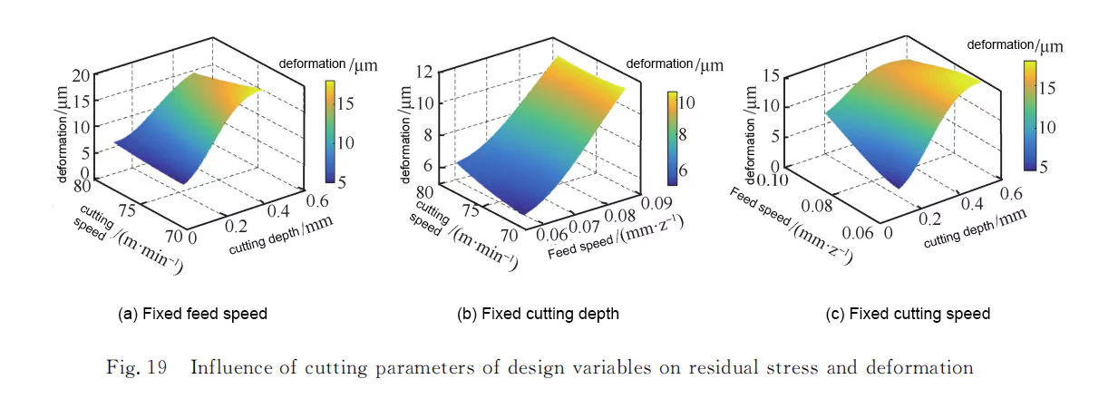
The results proved that the optimal combination of cutting parameters under the given constraints was obtained by the genetic algorithm as a feed rate of 0.0599 mm/z; cutting speed of 72.5627 m/min; and milling depth of 0.1090 mm.
In the machining process, the optimized milling parameters can not only reduce and control the machining deformation of thin-walled parts to meet the requirements of machining accuracy but also improve the machining efficiency, so the reasonable optimization of milling parameters is of great significance to manufacturing.
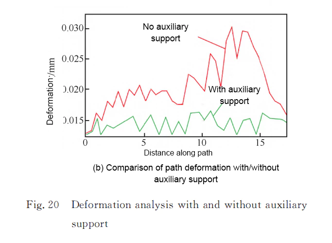
2. Assistive Support Technology
In the milling of thin-walled parts, the use of auxiliary support technology is mainly to improve the rigidity of thin-walled parts in the machining process, thereby reducing the elastic deformation in the machining process.
Auxiliary support technology to control the deformation of thin-walled parts of the research are mainly phase change material auxiliary support and mirror image milling processing 2 categories.
2.1 Auxiliary support based on phase change of materials
To solve the deformation, low melting point material was injected into the structural cavity to assist milling.
The use of phase change auxiliary support can improve the rigidity of thin-walled parts, thus improving the machining accuracy of thin-walled parts, but it will increase the machining process steps and reduce the machining efficiency to a certain extent.
2.2 Mirror Milling System
The so-called mirror milling system is composed of two synchronous movements of the horizontal machining center and flexible fixture, two machine tool spindle heads a support head, the other the machining head, the two synchronous movements, as mirror distribution in the machining of the workpiece on both sides of the principle of Fig. 21 shows.
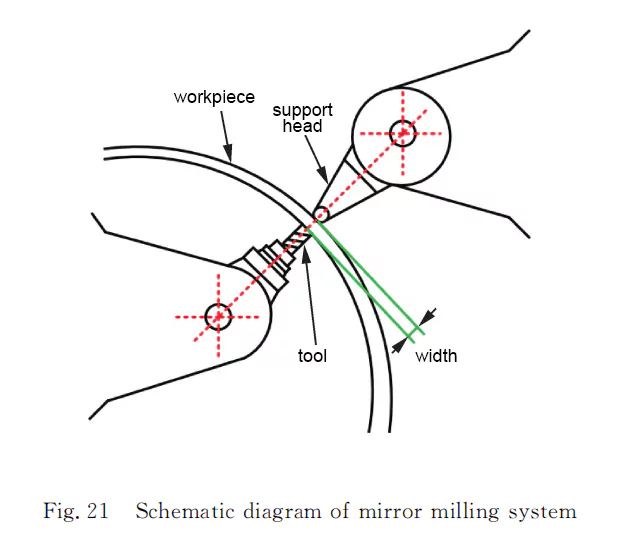
At present, France’s Dufieux Industrue and Spain’s M. Torrs company are the world’s leading manufacturers of mirror milling equipment.
The use of mirror milling can improve the rigidity of thin-walled parts, can reduce the deformation of the milling process; can also avoid the repeated positioning errors caused by multiple clamping to ensure machining accuracy and improve the processing efficiency.
However, the current mirror milling parts are mainly thin-walled flat plates, for the complex shape of thin-walled parts still needs further research.
3. High-speed cutting
The concept of high-speed cutting in 1931 was first put forward by the German physicist Carl.J.salomon; after many scholars’ efforts to make high-speed cutting theory more mature and complete. The main content of the theory is: in the traditional range of cutting speed, cutting temperature and cutting force with the increase of cutting speed and become larger, when the cutting speed is more than a value, cutting temperature and cutting force with the increase of cutting speed but will reduce, can solve the elastic deformation and residual stress deformation.
High-speed cutting on the deformation process, as shown in Figure 22, high-speed cutting simplified model, the first deformation zone is reduced, the shear angle becomes larger; the second deformation zone of the contact length is reduced, the front face of the front blade by the load reduces the role of high-speed cutting, so the cutting force is greatly reduced; and then due to the chip discharge speed is very high, most of the heat in the cutting process is taken away by the chip, reducing the cutting temperature.
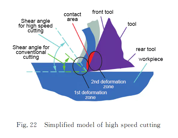
From the above analysis of high-speed cutting: due to the reduction of cutting force, in the processing of thin-walled parts, the tool-workpiece deformation will be correspondingly small, improving the size and shape of the parts and accuracy; because most of the heat is taken away by the chips, HSM compared to conventional cutting, the temperature rise of the workpiece slowed down, workpiece thermal deformation is reduced.
In high-speed cutting, the tool’s overhang is generally shorter, has good rigidity, small axial depth of cut, large radial width of cut, and high cutting efficiency, suitable for thin-walled parts processing.
Therefore, high-speed cutting of thin-walled parts with high precision is the development trend of future manufacturing technology.
4. CNC compensation technology
Under the action of cutting force on machined parts, elastic deformation of the parts will occur, and with the continuous removal of material, after the tool is passed, part of the workpiece will rebound, and the phenomenon of letting go of the tool will occur, resulting in thin-walled parts that are thicker on the top and thinner on the bottom.
According to the degree of deformation, the tool will be an additional deflection to solve the elastic deformation of thin-walled parts.
4.1Real-time deformation error compensation based on dynamic features
For the cutting force caused by the elastic deformation of the workpiece error compensation problem, a dynamic feature-based real-time deformation error compensation method can be used to establish a dynamic feature model, and then calculate the amount of deformation according to the dynamic feature model, which can realize the elastic deformation machining error compensation based on the function block.
4.2 Offline Active Compensation Method
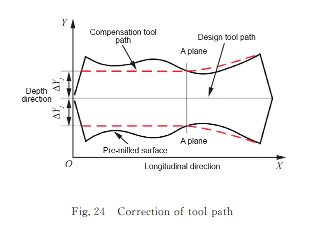
Deformation due to the low stiffness of thin-walled parts, is caused by the phenomenon of letting go of the tool under the action of the force. The data is processed through a hybrid programming method of VC++ and MATLAB, which generates intuitive graphs and modifies the tool trajectory.
To solve the problem of thin-walled parts on the thick under the thin, in the CNC programming, in the tool based on the original walking tool, according to the degree of deformation, so that the tool to carry out additional deflection, to compensate for the amount of rebound generated by the letting tool, can be compensated through the numerical control technology, a cutting tool will be the removal of the residual material and can ensure the machining accuracy of thin-walled parts.
At present, solving the deformation problem of thin-walled parts, through process optimization, clamping layout, auxiliary support technology, high-speed cutting technology, and CNC compensation technology to analyze, so as to ensure that the machining accuracy of thin-walled parts in a particular part can achieve the desired results.
Difficult
Tool path compensation is not only all changes in the tool position that can be realized compensation but also the need to change the tool attitude, if the compensation path is not smooth, the actual machining accuracy will be reduced, and other issues, it is difficult to promote to the general application.
Can AI help improve
Based on artificial intelligence algorithms can improve computational efficiency, but artificial intelligence algorithms need to train the model, the training model is carried out under specific parameters, if the parameters change accordingly, it is necessary to retrain, so artificial intelligence algorithms to detect machining deformation as well as the application of guided machining is subject to certain limitations.
Future technology-Digital Twin
The convergence of new-generation technologies like the Internet of Things, big data, and cloud computing with manufacturing has given rise to the concept of digital twins. These twins, virtual replicas of physical entities, enable seamless interaction between the physical and digital worlds, leading to intelligent manufacturing processes.
In the context of machining, digital twins play a crucial role in predictive maintenance and quality control. By leveraging data analytics, simulation models, and real-time feedback mechanisms, they empower manufacturers to monitor tool wear, predict machining outcomes, and optimize processes, particularly in thin-walled machining applications.
One notable advancement is the integration of analytical and finite element models with sensor data, culminating in the development of digital twin-based platforms. These platforms enable the prediction and control of thin-walled part deformations, addressing a significant challenge in precision manufacturing.
Through sophisticated data fusion techniques, these platforms accelerate deformation prediction and facilitate real-time control, ultimately enhancing machining accuracy. They consist of multiple layers, including physical entity layers, twin information layers, and cloud decision layers, each contributing to the overall intelligence and adaptability of the system.
The benefits of digital twin-driven approaches are manifold. They offer real-time insights into machining processes, facilitate adaptive decision-making in response to changing conditions, and integrate intelligent algorithms to optimize performance and reduce costs.
In essence, digital twins represent a paradigm shift in manufacturing, empowering industries to achieve unprecedented levels of precision, efficiency, and control. By bridging the gap between the physical and digital realms, they pave the way for a new era of smart manufacturing.
Conclusion
Generally speaking, processing thin-walled parts is a very challenging job. From the source, thin-walled processing must be considered when designing products. This is an important factor in making successful products. Of course, under the premise that there is no choice, from a practical perspective, a suitable processing solution is the most realistic choice for enterprises and customers.