How to process titanium alloy thin-walled parts with a length-to-diameter ratio?
Titanium alloys are more widely applied in aerospace due to their high strength, low density, preservative, high-temperature resistance, good weldability, etc. It belongs to classic materials of tough machining, bad thermal conductivity in the machining process, high viscosity during cutting, small elastic modulus, easily deforming and twisting, and precision is difficult to guarantee.
When machining, these parts of the thin walls are less than 1mm or length-to-diameter ratio is more than 10 have poor stiffness, are difficult to clamp, and easily process deforming by cutting force.
It is mainly difficult to process the thin walls of titanium alloys of big length-to-diameter ratio, which is poor thermal conductivity, bad stiffness, and weak bending resistance, processing affected by machining force, cutting thermal, etc, easily raises issues of bend, taper default and waist drum shape.
To this end, these processing problems are solved through equipment optimization, process solution improvement, processing parameter adjustment, and deformation straightening.
Part structure and processing requirements
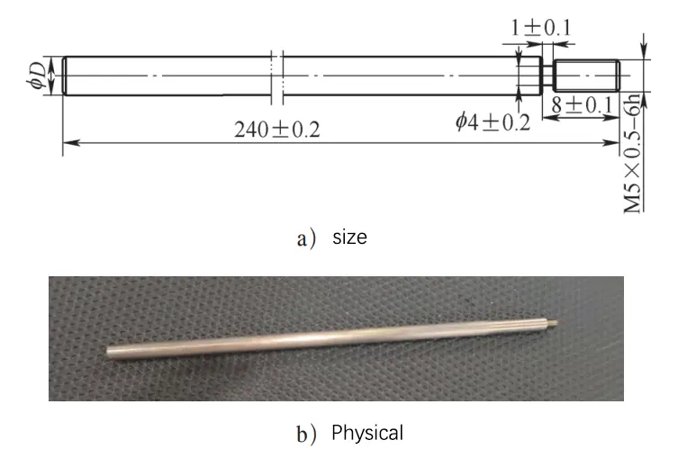
The material of a part is TC6-M titanium alloy (double annealing). The part size is shown in Figure 1. The aspect ratio is close to 40, and the wall thickness is less than 0.5mm. It is a thin-walled structure with a length-to-diameter ratio.
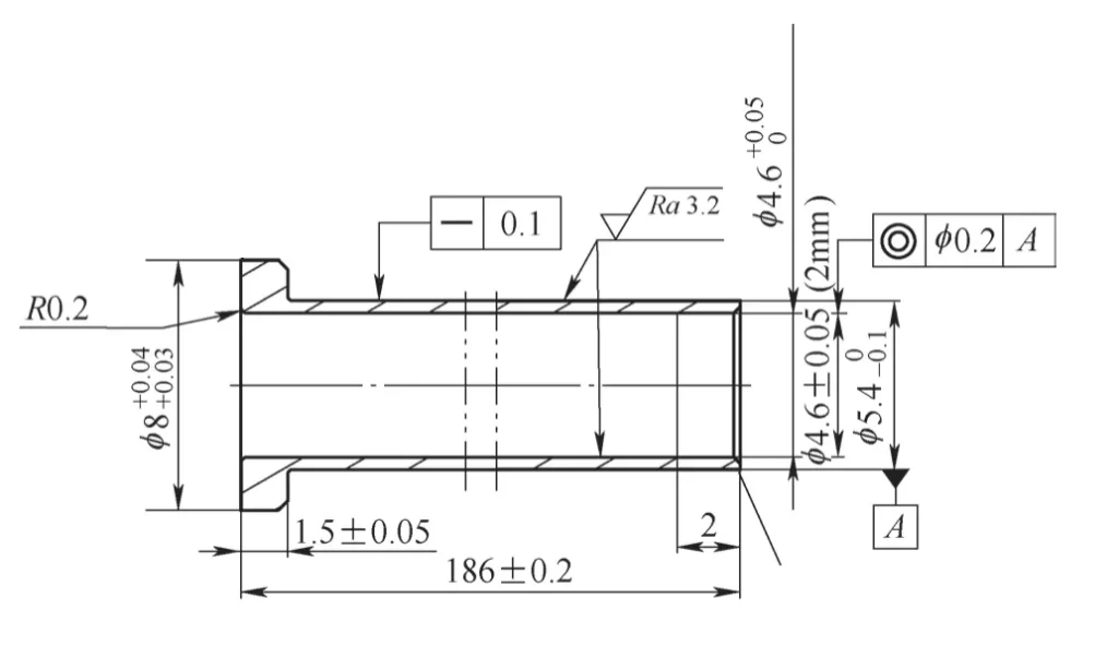
The inner hole is φ (4.6±0.05) mm, the total length is (186±0.2) mm, and the surface roughness value is Ra=3.2μm. The outer circle of the large end is φ 8+0.04 +0.03mm, and the size is strict; the outer circle of the small end is φ5.4 0 -0.1mm, and the straightness is required to be 0.1mm.
1. Material Analysis
TC6 titanium alloy is a martensitic α-β two-phase titanium alloy with good comprehensive performance. Its nominal composition is Ti-6Al-2.5Mo-1.5Cr 0.5Fe-0.3Si. It has high room temperature strength. The chemical composition is shown in Table 1. It can work for more than 6000 hours at below 400℃ and 2000 hours at below 450℃.
2. Analysis of processing difficulties
The parts have simple structures and high dimensional accuracy requirements. The clamping force and radial cutting force can easily cause the parts to deform, making clamping difficult. The poor cutting processability of titanium alloy materials also increases the difficulty of designing process solutions.
The processing of parts with length-to-diameter ratios usually adopts the clamping method of chuck clamping and rotary center top clamping. In general processing, it is necessary to install a follower rest and a center rest to balance the radial cutting force and reduce the deformation of the workpiece during processing.
Due to the limitations of the outer circle and length dimensions, the parts shown in Figure 1 cannot be directly clamped by a center rest and a follower rest. Therefore, improving the clamping rigidity of the parts and reducing bending deformation are the main measures to ensure the dimensional accuracy of the parts.
Processing technology
1. Process design
1) A 10mm margin is reserved in the axial direction of the part as a process addition for clamping, reducing the influence of the clamping force on the outer diameter accuracy of the clamping part of the part.
2) The CNC turning process leaves a 0.2mm margin for the φ 8mm outer circle and a 2mm margin for the φ 5.4mm outer circle to improve the clamping rigidity of the deep hole drilling process of the part. The outer circle after turning is used as the positioning reference for the deep hole drilling process. The inner hole is deep-drilled by a high-precision deep hole drilling machine PT2/750 to ensure the hole size tolerance.
3) When the CNC turning fine turning the outer circle, the inner hole is used to locate the through-shaft to improve the rigidity of the part and reduce bending deformation. This process is the most difficult to process.
4) When the part is processed to the final wall thickness, in order to reduce the deformation caused by cutting addition, the wire cutting in the EDM is used to remove the process addition, the bench is used to process the R0.2mm fillet, and the end face is polished and the electro-etching layer caused by the EDM is removed.
2. Processing process
Processing process: material preparation → CNC turning → deep hole drilling → CNC fine turning → wire cutting → benchwork → ultrasonic cleaning → fluorescent flaw detection → inspection → rust prevention and sealing.
Use φ 15mm×200mm titanium alloy bars, CNC lathe turning the outer circle to φ 10mm×198mm, deep hole drilling positioning reference, deep hole drilling once drilling φ (4.6±0.05)mm hole, CNC fine turning the outer circle with inner hole positioning, finally use wire cutting to remove process additional amount, benchwork deburring and clean the parts, and then inspect and hand over to the warehouse.
Problems and analysis in processing
1. Problems
When CNC fine turning the outer circle after deep hole drilling, there are penetration problems caused by outer circle size tolerance and coaxiality tolerance.
(1) Fine turning outer circle method 1
①5 steps: two top rough turning outer circles, process parameters are speed n=800r/min, feed f=0.14mm/r, and removal of 0.2mm.
②10 steps: one clamp and one top method (self-made plug), process parameters are rough turning speed n=800r/min, feed f=0.14mm/r, cutting to φ 5.56mm, removing 2mm; fine turning speed n=800r/min, feed f=0.1mm/r, cutting to φ 5.36mm.
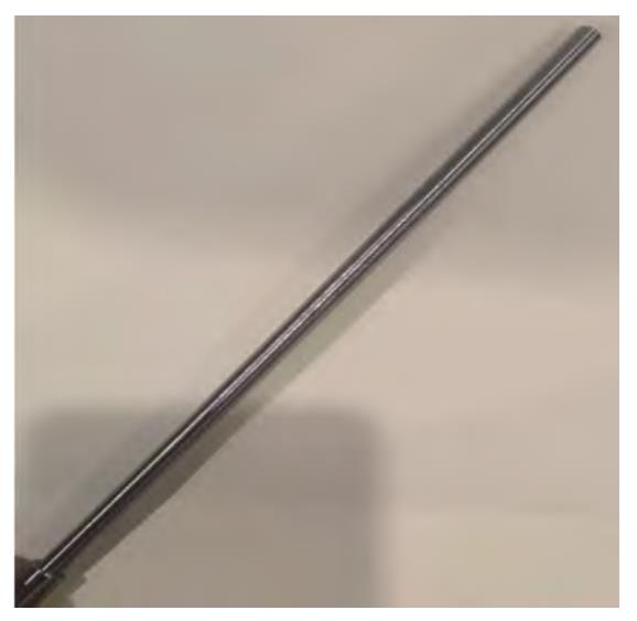
After turning, the outer circle of the part deforms the tool and the shape is waist drum-shaped (see Figure 2). The measured size of the part in the middle is φ 5.8mm, and the two ends are φ 5.5mm; the outer surface roughness value Ra>6.3μm.
(2) Method 2 for fine turning of outer circle
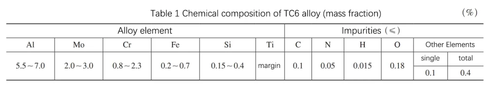
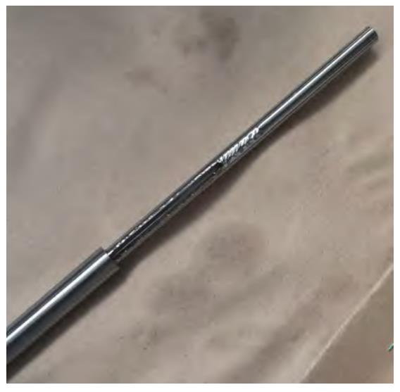
Improve the fine-turning tool path. By checking the deformation and position of the outer circle, according to the deflection of 0.3mm (φ 5.8mm-φ 5.5mm) in the diameter direction, the oblique line is taken from one end of the part to the middle position during programming to compensate for the tool letting phenomenon. The inner hole penetration of the part after processing is shown in Figure 3.
2. Problem Analysis
(1) Cause Analysis
The main reason why the outer circle of the part is in the shape of a waist drum is that when the CNC lathe is turning the part, the part clamping adopts a one-clamp-one-top method, the part overhang is long, and the rigidity is poor.
The cutting force during turning can be decomposed into axial cutting force, tangential cutting force and radial cutting force. The axial cutting force and tangential cutting force cause the workpiece to produce a slight longitudinal deformation, which has little effect on the workpiece;
The radial cutting force is perpendicular to the axis of the part, causing the part to bend and deform, resulting in the smallest cutting amount in the middle of the part, and the part is in the shape of a waist drum after processing.
The penetration of the inner hole of the part is mainly caused by the coaxiality of the inner hole and the outer circle of the part. After the deep hole drilling is used to process the inner hole, the part has been bent and deformed. The deep hole drilling process has no straightness requirements for the outer circle. After the deep hole drilling, the inner hole and the outer circle are not coaxial. The cutting allowances are different when the two tops turn the outer circle, resulting in local penetration.
(2) Mechanism Analysis
The part is clamped in a one-clamp-one-pushing way. The total length of the part is 186 mm. When the CNC lathe is turning the outer circle, the overhang is long. During the turning process, the part is affected by the radial cutting force and the overhang length, resulting in bending deformation. The mechanical model of the CNC lathe turning the outer circle is shown in Figure 4.
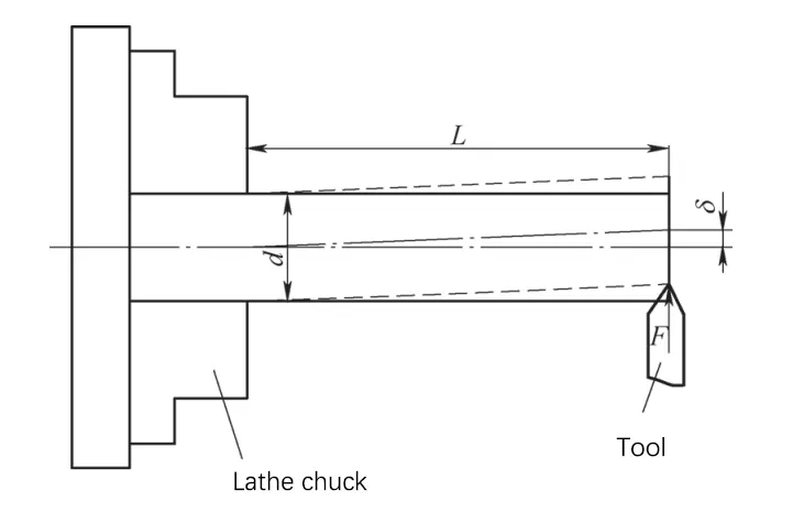
According to material mechanics, when turning the outer circle, the calculation formula for the deformation δ at the end of the part is

(1) In the formula, δ is the deformation (mm);
F is the radial cutting force of the tool on the workpiece (N);
L is the overhang length, which refers to the distance between the workpiece clamping point and the tool action point (mm);
E is the elastic modulus of the workpiece material (N/mm2), and d is the workpiece blank diameter (mm).
It can be seen from formula (1) that when the part material and workpiece diameter are constant, the factor that has the greatest impact on the part turning deformation δ is the overhang length L, followed by the radial cutting force F.
Improvement of processing technology
1. Equipment optimization
Processing characteristics of CNC longitudinal lathe: the spring chuck in the spindle clamps the bar material for rotation and axial feed movement, and the tool moves radially.
Since the tool’s motion trajectory is perpendicular to the axis of the workpiece, that is, the workpiece rotates and moves during turning, the turning tool does not need to move with the workpiece, and the cutting tool is always kept in the clamping position of the spindle and the workpiece, so that the part processing part is always in a position with good rigidity. When the overhang length L decreases with the movement of the part turning tool, the deformation δ decreases exponentially, so the longitudinal lathe is more suitable for processing parts with a length-to-diameter ratio.
There is an essential difference between longitudinal lathes and conventional lathes. Conventional lathes rely on the movement of the tool to complete the turning of excess blanks during processing. For precision slender shaft parts, conventional lathes obviously cannot meet the processing needs.
The aspect ratio of this part is close to 40, which is more suitable for processing on CNC longitudinal lathes. When longitudinal cutting equipment processes parts, an additional length of the feeding part must be left (>200mm). When processing this part on a conventional lathe, the additional length of the process only 15mm.
Since the part material is TC6 titanium alloy, which is expensive, a large amount of additional length is reserved for the part when it is processed on a longitudinal cutting lathe. The process cost is too high, and the work-in-progress that has been processed by the deep hole drilling process on-site cannot be processed.
Therefore, to solve the clamping problem when processing on a longitudinal cutting lathe with the same stock length of the part, the following measures are mainly taken.
1) Process M5×0.5-6H internal thread at the additional position of the part, with a screwing length of 9mm.
2) Design a feed rod (see Figure 5) to replace the process addition. The feed rod material is 45 steel, 240mm long with M5×0.5-6h external thread, the outer diameter of the feed rod should be the same as the outer diameter of the part before longitudinal cutting, and the spring chuck should be clamped reliably.
3) To improve the rigidity of the part, the outer diameter of the feed rod is 8.5mm according to the nominal value of the outer diameter of the part (the lathe spring chuck specification is φ8.5mm), and the dimensional tolerance is divided into 1 group for every 0.02mm, and a total of 5 groups.
2. Adjust cutting parameters
TC6 titanium alloy material has poor thermal conductivity, high material viscosity, and low elastic modulus during cutting, and the workpiece is prone to large deformation.
When cutting titanium alloy, the cutting temperature near the cutting edge is high, and the titanium element is highly active, which is easy to react chemically with oxygen, aggravating the wear of the tooltip. By comparing and testing multiple brands of blades, the tool and cutting parameters of TC6 titanium alloy material processed by CNC longitudinal lathe are optimized. Mitsubishi blades are used for turning, model CCGT09T301M-FS MP9005;
The cutting parameters are speed n=900r/min, and feed rate f=0.02mm/r.
After processing, the parts can meet the surface roughness value Ra=1.6μm and the outer circle straightness 0.3mm, but cannot meet the outer circle straightness 0.1mm. At the same time, it is difficult to ensure the coaxiality φ 0.2mm of the inner hole to the outer circle.
3. Optimize the process plan
(1) Deformation straightening The straightening process is a processing method to eliminate the radial bending of shafts, rods, and tube parts. The parts have been bent and deformed after deep hole drilling, and a straightening process needs to be added.
After deep hole drilling, the outer circle allowance wall thickness is greater than 2mm. The fitter uses the pressure point straightening method, and the part straightness is ≤0.15mm.
Since the outer circle straightness after longitudinal cutting is 0.3mm, it cannot meet the coaxiality requirements of the drawing. Therefore, it is necessary to straighten the finely machined φ 5.4mm outer circle. At this time, the wall thickness of the part is only 0.4mm. Directly pressing on the outer circle surface of the part for straightening is likely to cause surface deformation of the part.
For this reason, a straightening fixture is designed as shown in Figure 6. The pressure point straightening method is used. The part is placed on a double V-shaped fixture for positioning, and the pressure head is designed as a bronze semicircular ring.
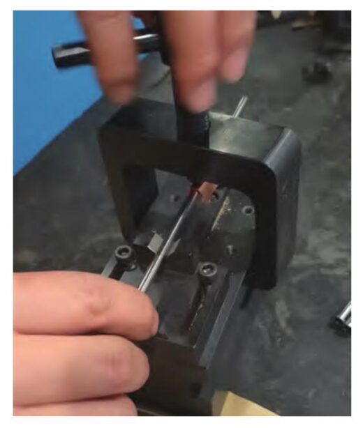
Bronze is softer than titanium alloy. The pressure head is changed to a torus to increase the contact area. Before straightening, first check the straightness of the outer circle and mark the bending point with a red pen. Then straighten it. Visually check that there is no indentation on the outer circle of the part. Check that the outer circle and inner hole diameter and coaxiality of the part meet the requirements of the design drawing.
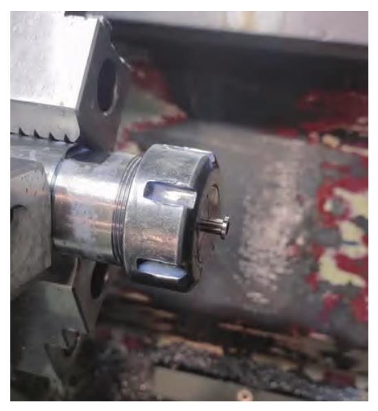
(2) Fine turning of the outer circle and additional cutting process. Fine machining of the outer circle of the large end φ 8+0.04 +0.03mm is performed. The additional cutting process is completed and R0.2mm polishing is completed and the sharp edge of the large end is retained.
First, use the machining center tool holder for clamping. Use the arc surface of the spring chuck to clamp the part close to the outer circle of the large end. Increasing the contact area can reduce the clamping deformation. Then clamp the tool holder on the self-centering chuck of the CNC lathe (see Figure 7). Use the CNC lathe to fine-turn the outer circle of the large end φ 8+0.04 +0.03mm, and remove the additional process to ensure the total length of the part. Polish the left end face of the part R0.2mm and retain the sharp edge.
3. Improved process flow and processing effect
The content of parts preparation and CNC turning rough processing remains unchanged. The deep hole drilling process is divided into rough and fine processing. The hole diameter is controlled by φ (4.6±0.05) mm, and then the parts are straightened to ensure the straightness of 0.15mm. The CNC turning process is added-turning the outer circle to φ 8.5mm, and at the same time, the process internal thread is processed within the process additional length range of the parts, and the feed rod is installed.
The CNC longitudinal cutting lathe is used to fine-process the φ 5.4mm outer circle. After longitudinal cutting, the straightness of the parts is straightened to 0.1mm, and finally, the process additional is removed by the CNC lathe.
The parts are cleaned and delivered to the warehouse after non-destructive testing. Improved process flow: material preparation → CNC turning → deep hole drilling → straightening → CNC turning → longitudinal cutting processing → straightening → CNC turning → ultrasonic cleaning → fluorescent flaw detection → inspection → rust-proof sealing.
According to the improved process plan, 2 batches of 60 parts were processed, and 59 parts were qualified. The parts have been assembled and verified to meet the product performance requirements.
Conclusion
This paper aims at the processing difficulties of titanium alloy thin-walled parts with length-to-diameter ratio. It explores a reasonable process flow through improvement measures such as equipment optimization, process improvement, cutting parameter adjustment, and deformation straightening.
The key to processing is to improve the rigidity of parts and solve the problem of part deformation.
For parts that the center frame cannot clamp, CNC longitudinal cutting equipment can be used for processing to improve the deformation problem caused by cutting force in the traditional processing of parts.
Due to the high material cost of titanium alloy parts, special feeding tooling can be designed to reduce the additional length of CNC longitudinal cutting process;
The cutting tools and cutting parameters of titanium alloy materials can be used universally with parts of the same material with good rigidity, and the process parameters need to be adjusted appropriately with the specific structure of the equipment and parts;
The straightening process has an improved effect on the deformation of thin walls with a length-to-diameter ratio. During straightening, the tooling adopts an inner ring pressure head to increase the contact area, which solves the problem of local size tolerance or appearance damage of parts.