Tool Setting Methods in CNC Machining
why does CNC machining need tool setting?
CNC lathe or milling machine in the processing of parts is based on the technical requirements of the parts map to develop a processing technology program, and then use the prescribed program format and code to write the corresponding CNC program, the CNC program to control the movement of the moving parts of the machine tool to complete the processing of parts.
CNC program based on the coordinates of the nodes on the parts map for the preparation of the node’s coordinates of the position of the corresponding tool according to the establishment of the workpiece coordinate system to determine the spatial orientation. In the CNC machine establishing the workpiece coordinate system requires a tool setting process, this process will have a direct impact on the machining accuracy of the parts and machining efficiency.
Tool setting Method
In this paper, the shaft parts commonly use an external contour tool and an internal contour tool as an example, through the CNC simulation machining software to explore the commonly used types of turning tool setting methods.
External contour tool setting method
Shaft parts commonly used in external contour machining tools have a cylindrical turning tool, external groove tool, and external threading tool, etc., are generally convenient and quick, without the need to add the auxiliary tooling test cutting method for tool setting.
1. Cylindrical turning tool setting
There are many types of cylindrical turning tools, such as straight-head cylindrical turning tools, 45 ° elbow cylindrical turning tools, 90 ° elbow cylindrical turning tools, and so on. 90 ° elbow cylindrical turning tool as an example, open the Swarthmore CNC simulation software, blank selection FANUC0iT system default material 08F mild steel.
The turning tool will generally be the origin of the workpiece coordinate system established in the center of the right end face of the workpiece, the workpiece axis for the Z direction, and the radial for the X direction. Before the test cutting of the cylindrical turning tool (T01), first start the spindle, enter “M03S300” in the [MDI] mode and execute, as shown in Figure 1 (a); and then move the tool through the manual feed mode to complete the test cutting of the right end face of the workpiece, as shown in Figure 1 (b).
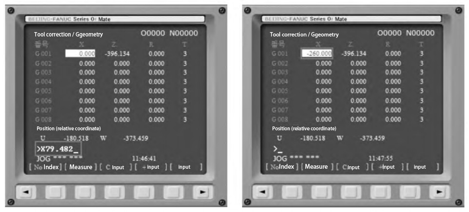
Open the [OFFSETSETTING] function of the control panel, and in the [tool correction/geometry] interface, define the Z coordinate of the tool’s current location as “Z0”, as shown in Fig. 2 (a), and click the gray square button under [Measurement], and the result of measurement is shown in Fig. 2 (b), thus the Z-axis tool setting of the external turning tool is completed. This completes the Z-axis tool setting of the cylindrical turning tool.
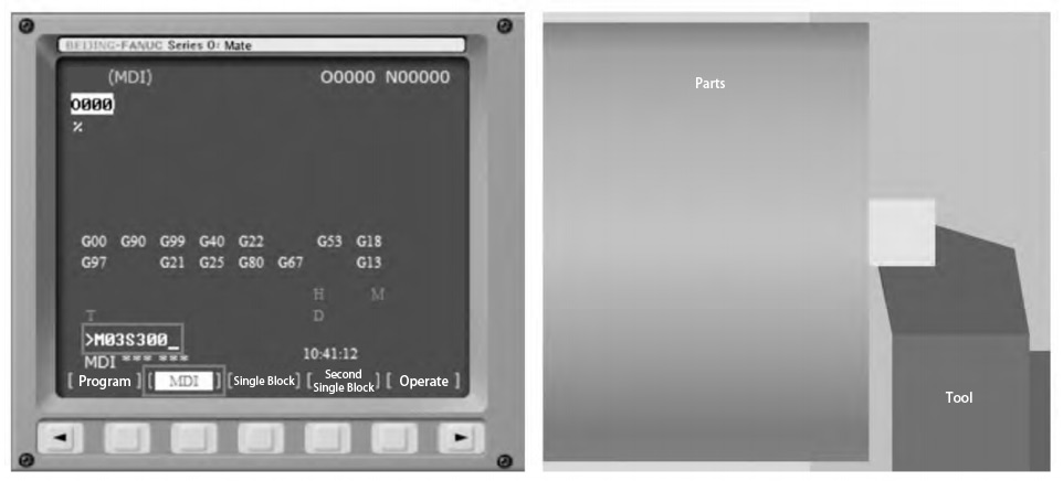
Figure 1 Z-axis tool setting
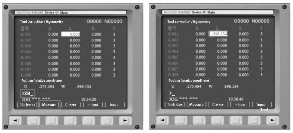
Figure 2 Z-axis tool setting parameters
The tool will back off in the +X direction, and in the process of backing off, the X-axis trial cutting positioning will be completed at the same time, as shown in Fig. 3 (a); after positioning, the tool will feed into the -Z direction to complete the cylindrical trial cutting, as shown in Fig. 3 (b).
After a certain axial distance of cylindrical test cutting, the tool withdraws from the appropriate distance along the + Z direction, as shown in Figure 4 (a); stop the spindle rotation, open the main menu of the [Workpiece Measurement] command, with vernier calipers to measure the diameter of the outer diameter of the test cutting, as shown in Figure 4 (b).
Open the [tool correction/geometry] interface, the tool is currently located in the X-coordinate defined as shown in Figure 4 (b) of the measured diameter of the outer circle, and enter “X79.482”, as shown in Figure 5 (a); click on the [Measurement] under the gray square button, get the figure shown in Figure 5 (b) of the measurement results.
To this end, the external turning tool to the tool is complete, and the tool carrier is to carry out the [return to the origin] operation.
Operation.
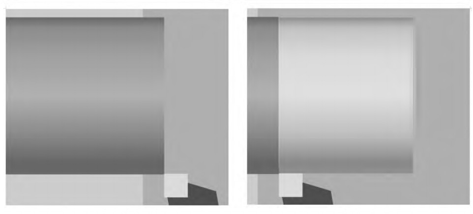
Figure 3 X-axis test cutting tool setting
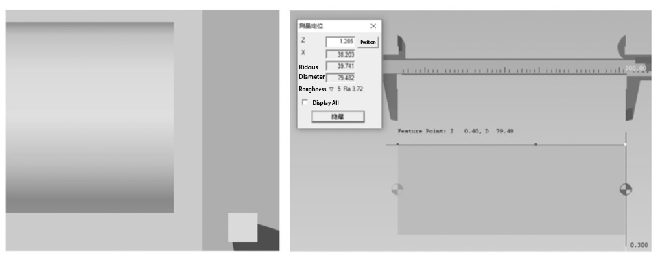
Figure 4 X-axis tool setting process
2 Tool setting for external groove cutter
Turn the tool holder clockwise, and turn the external groove cutter (T02) to the machining position, the external groove cutter is also to complete the tool setting by trying to cut the end face and outer circle.
Start the spindle, and move the tool holder, so that the blade of the external groove cutter gently touches the end face of the workpiece, as shown in Figure 6 (a); keep the tool immobile, open the parameter setting page, select the [002] position of the [number], and enter “Z0” for [measurement], as shown in Figure 6 (b).
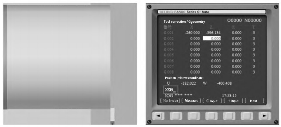
Figure 6 Z-axis tool setting for external groove cutter
Adjust the tool position so that the external grooving cutter will make a test cut on the outer circle of the workpiece, as shown in Fig. 7 (a); then back out the tool in the +Z direction, and measure the diameter of the outer circle that has been test cut by the external grooving cutter after stopping the rotation of the spindle, and input the data obtained from the measurement to the corresponding position, such as “X79.130” as shown in Fig. 7 (b) and click [Measurement] in the lower part of the tool. Click on the gray square button under [Measurement]. At this point, the external groove cutter has finished tool setting, and the tool holder will be operated back to the home position.
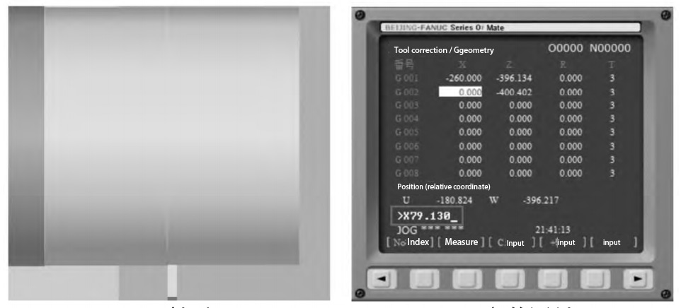
Fig. 7 X-direction tool setting of external grooving cutter
3 Aligning the external threading cutter
Turn the tool holder clockwise again, turn the external threading cutter (T03) to the machining position, and move the tool holder. When the tool is close to the workpiece, reduce the feed speed and adjust it until the tip of the external threading tool is flush with the end face of the workpiece, as shown in Fig. 8 (a), pause the feed movement of the tool holder; open the parameter setting interface, select the [003] position of the [No.], and assign “Z0” to the tool’s current position for “Measurement”.
In the manual feeding mode, fine-tune the tool position, so that the tip of the external threading tool slightly touches the surface of the outer circle has been processed, as shown in Figure 8 (b), and in the parameter setting interface be the current position of the tool is defined as the aforementioned 1.2 external groove cutter (T02) try to cut the outer circle of the diameter of the workpiece measured after. At this point, the external threading tool alignment is complete, the tool holder needs to be [back to the origin] operation.
Figure 8 External threading tool alignment
The above are the shaft parts commonly used in the external contour machining tool alignment process.
Internal contour tool setting method
Shaft parts commonly used in internal contour machining tools have a hole turning tool, internal groove cutting tool internal threading tool, etc., these tools are also tool setting workpiece coordinate system origin established in the workpiece right end face center point of the process.
1 Bore turning tool alignment
The Bore turning tool (T01) commonly known as the “boring tool”, is a boring tool to the tool before the drill has completed the center hole drilling process.
Open the main menu of the [machine tool operation] command under the [fast positioning] function, select the center of the workpiece, click the [OK] button, get the machining window shown in Figure 9 (a); open the [tool correction/geometry] interface, the current position of the boring tool is assigned to the value of “X0”, and its [Measurement] operation, the results are shown in Figure 9 (b). The result is shown in Figure 9 (b).
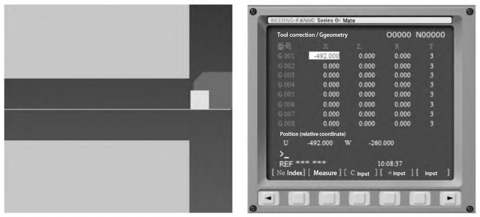
Figure 9 Boring tool X-axis alignment
Fine-tune the position of the boring tool so that it slightly touches the right end face of the workpiece, as shown in Figure 10 (a); open the parameter setting interface, assign the current position of the boring tool as “Z0” and measure it, and the result of the operation is shown in Figure 10 (b). At this point, the internal hole turning tool (boring tool) tool setting is complete, the tool holder needs to be [back to the origin] operation.
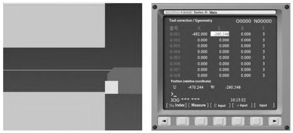
Figure 10 Boring tool Z-axis tool setting
2 Internal grooving tool setting
Turn the tool holder clockwise to turn the internal grooving tool (T02) to the machining position. After starting the spindle, use the [Quick Positioning] command to move it to the center of the right end face of the workpiece as shown in Fig. 11 (a), and assign the current position to “X0” in [002] of the [Tool Correction/Geometry] interface and measure it.
Slightly move the internal grooving cutter so that its tool position point touches the right end face of the workpiece, as shown in Fig. 11 (b), and assign the current position as “Z0” and measure. At this point, the internal groove cutter tool alignment is complete, the tool holder needs to be [back to the origin] operation.
3 Tool setting for the female threading tool
Turn the tool holder clockwise to turn the internal threading tool (T03) to the machining position. After starting the spindle, use the [Quick Positioning] command to quickly move it to the center of the right end face of the workpiece, as shown in Fig. 12 (a). In the [tool correction/geometry] interface, assign the current position as “X0” in [number] [003] and measure.
Fine-tune the position of the internal threading tool so that the tip of the internal threading tool is flush with the right end face of the workpiece, as shown in Fig. 12 (b). Pause the tool feed motion, assign the current position as “Z0” in [Number] [003] of the [Tool Correction/Geometry] screen, and take measurements. At this point, the internal groove cutter matching is completed, and the tool holder needs to perform the [Return to Home] operation.

Figure 11 Internal grooving tool setting

Figure 12 Internal threading tool alignment
The above is the process of tool setting for internal contour machining tools commonly used for shaft parts.
Conclusion
CNC turning before processing, the need to establish the workpiece coordinate system, and set the accuracy of the workpiece coordinate system operation is the main factor affecting the accuracy of parts processing and processing efficiency. In this paper, the shaft parts processing in the common external contour turning tool and internal contour turning tool as an example, a detailed investigation of the various types of tool setting methods, operation process, and precautions, to the various types of common external contour turning tool, internal contour turning tool setting lists the theoretical basis and simulation reference for operators engaged in CNC turning process provides a reference.
“A blog like this is a true discovery! Thank you for providing a reliable and well-organized space for information seekers!”