What is a drive center?
CNC lathe processing parts mainly include shafts, sleeve parts, etc. For these parts, if you undertake the clamp method, which is one dead center and one clamp, you must stop the lathe and adjustment parts and then finish your work. The old method wastes time and the boss must be depressed too.
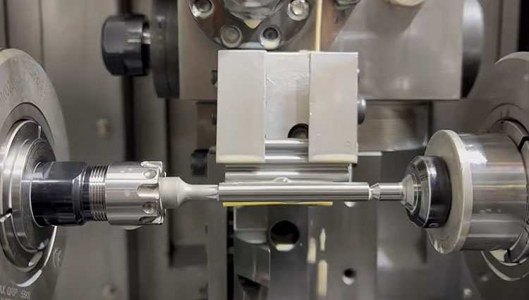
Engineers researched a new technical, lathe drive center, one clamped and finished all sizes of shaft parts machining. The use of a face driver center to clamp shaft parts not only completes the machining of all external surfaces of the workpiece under one clamping condition, thus shortening the clamping auxiliary time and improving the positional accuracy between the relevant surfaces of the workpiece but also converts the increase in the spindle speed of the machine tool from being restricted by the limiting rotational speed of the hydraulic cylinder to being restricted by the limiting rotational speed of the tailstock center. Undoubtedly, it is technically easier to increase the speed of the tailstock center than to increase the speed of the rotary hydraulic cylinder.
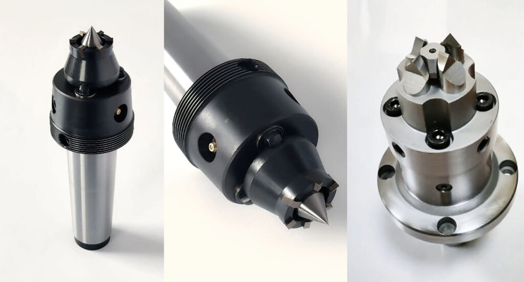
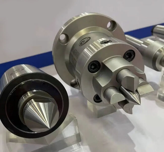
The drive center used three or more driving tool edges embedded into part end face, and make it rotate. It is different from the plum blossom thimble center that is not positioned on the center hole of the part, drive center location in the center so that its application is wider. The tool can easily be processed from part two sides because the driver center top is less than the part’s diameter.
The end face drive center, at present, used most popular includes two types, mechanical and hydraulic. Its principle: depends on the drive claw that is embedded into the part surface making workpiece rotation with the machine spindle, and replaces to chicken heart chuck and normal chuck at the processing shaft.
Advantages:
- one clamping and can be processing whole parts, don’t need to reclamp and then save at least twice as much clamping assistance time.
- same diameter part machining doesn’t continuously tooling trace questions, part surface’s relative position to be machined has high precision.
- clamp force shouldn’t be influenced by the machine spindle rotation speed, especially suited for requests for high-speed cutting.
- still capable ensure steady clamping when part end face and centerline have big tolerance.
- overall machined with high efficiency, remarkably reducing the labor intensity of workers.
- have capable unloading or loading parts under don’t stop lathe condition, not only prompts manufacturing high efficiency but also reduces energy consumption and prolongs the life of the machine.
Application:
Brandly implies a middle small lathe or gearing machine, especially a CNC lathe, or a hydraulic lathe to machining brass, aluminum, steel, etc.
Mechanical face driven center
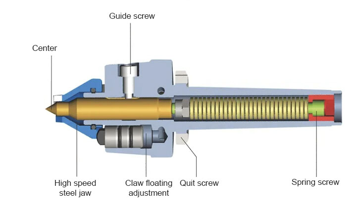
Mechanical face-driven centers are widely applied, and convenient for installation and use. Its center connects with a built-in spring and can move forward and backward, driven gear has no axis direction route, but has some amount of float to compensate for fluctuating workpiece face.
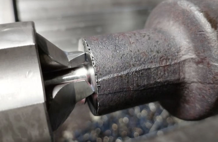
Clamp: tails tock center push workpiece to driver center – > the center hole of the workpiece end face and tail center to contact and position – > push the workpiece toward the driver center until into it – > workpiece and driver gear contact, and generate force each other – > finished processing
The lathe center runout is less than 0.02mm, after machined workpiece runout can reach 0.02~0.05mm.
Connect spindle methods:
- The Morse taper shank is directly connected to the inner hole of the spindle.
- lathe chunk clamping face driver center.
- Falan connects to the spindle.
Hydraulic end face driver center
The hydraulic end face driver center has higher precision of position and machining but still needs to connect to the spindle cylinder to use. Its center is fixed, driver gear is pushed by the cylinder to the workpiece end face through the connect construct.
Clamp: tails tock center push workpiece to driver center – > the center hole of the workpiece end face and tail center to contact and position – > start oil cylinder and push the pod forward – > pull pod push out connect construct, driver gear be pushed forward – > workpiece and driver gear contact, and generate force each other – > finished processing
The lathe center runout is less than 0.005mm after the machined workpiece runout can reach 0.01~0.03mm.
Installing the hydraulic end driver center requires removing the chuck or other fixtures, it needs fixed to the spindle head through the flange, and necessary to ensure the connection of the pull rod and forward or backward stroke match the machining required.
Difference between Mechanical or Hydraulic end face driver center
The center of the mechanic driver center slip fits its body, and it connects to the built-in spring will move backward when under pressure, and will reset when disposed of pressure. The driver gear is fixed relative to its body, but when a pair of driver gears, normally speak is 3~6, contact with the fluctuating face of a workpiece, it has an amount of float with each other and to ensures each driver gear touches the workpiece, and equal force each it.
The center of the hydraulic driver center is stationary, and the required to adjust the flange to calibration runout of the center is less than 0.005mm. The driver center and tail stock center combined with the fixed workpieces, and still need to depend on the pull rod’s force to push the driver gear to the workpiece end face, but the force of pull rods is not more than the tail stock.
From the install form, the mechanic type only required a fixed spindle that’s just done, but the hydraulic type still considers or weighs the linkage of the pull rod and driver center, ensuring sufficient stroke and the stability and safety of the force-bearing contact parts.
From the precision of the fixture, the hydraulic type is more than the mechanic type that is due to the center of the hydraulic driver center being stationary(runout is about 0.005mm), however, the runout of the mechanic type only reached 0.01~0.02mm. The machined precision of the Mechanic driver center can reach 0.01mm below if it is a good or ideal machining environment.
How to choose end face driver center?
The choice needs to consider some points below.
1) driver center type
According machining method and precision, have four to choose from.
Mechanic driver center: In normal lathe processing, the precision of the machined part can reach 0.02~0.05mm.
Hydraulic driver center: applied to high precision processing, the precision can reach 0.01~0.03mm.
Grinding drive center: used for cylindrical grinding.
Gear hobbing driving center: used for gear hobbing processing
2) Specifications
Need to consider when ensuring its specification: driver end workpiece outside diameter and chamfer, the maximum diameter of machining workpiece, central hole diameter of driver end, the maximum push force of tail stock, etc.
driver end workpiece outside diameter and chamfer: driver gear external diameter is less more workpiece effective diameter(attention chamfer needs to subtract)
the largest diameter: the diameter of the workpiece should not be more than the driver center external diameter twice times, the machining maximum diameter can be more than the driver center diameter forth times only when cutting small material once time or tail stock has enough pushing.
central hole size: The diameter of the hole should not be more than the size of the driver center diameter.
tail stock maximum push force: it can calculate be required minimum push force according to the workpiece, cutting specification, and center type. Alter cutting specification is required or a new driver center if the parameters of the machine are lower than the value of the theory calculated.
3) connect way
with the same drive center above to illustrate
① Mechanic driver center:
install to spindle inner hole(morse taper hole) with MT3, MT4, MT4, or etc of morse taper shank.
first, connect the pan(or custom) with the Morse inner taper hole fixed to the spindle, and then the driver center with the Morse taper shank installed to the Morse taper hole of the connect pan.
the driver center with flange(or custom) installed to spindle through the flange.
with chuck clamping driver center, at then can processing soft claw according to driver center clamped position.
② Hydraulic driver center
the driver center with flange(or custom) installed to spindle through the flange.
③ Grinding drive center
install to spindle inner hole(morse taper hole) with MT3, MT4, MT4, or etc of morse taper shank.
the driver center with flange(or custom) installed to spindle through the flange.
④ Gear hobbing driving center
the driver center with flange(or custom) installed to spindle through the flange.
Driver centers apply the need to correct choice type, rational set cutting specification, and machine parameter.
Accessories of end face drive center choose and change method:
The center of the driver center and gear is easily damaged, and changes on time when it is bad.
The function of the driver center is to position the workpiece, and then with the driver gear to clamp part end face when the driver center finished position to its center. The driver center damage is small and can be used for a long time because it doesn’t bear too much radial cutting force when the workpiece is processing, and the axis direction push force is constant too. It is necessary to change it if the driver center is damaged and influences precision at the processing workpiece.
The function of the driver gear is to rotate the workpiece with force(or friction) on each other of the center and end face of the part. It will undertake huge pressure and twist force on processing, and easily damage and break relative to the driver center. A lot of driver force decreases when the driver gear edge is lost, even leading to slippery between the center and workpiece in machining, and scratched part surface.
The influence factor of the lifetime of the driver center has the hardness of the workpiece, tailstock push force and cutting specification, its lifetime will be lower when that three-factor index is higher. To ensure the cutting processing for the taken hard workpiece, the tailstock push force needs to keep a standard, that requests suitable push force is a key role in maintaining a normal lifetime, a decreased lifetime when the tailstock push force is more than the standard. Otherwise, it will lead to insufficient driving force and slipping.
The methods of changing the driver center and driving gear vary depending on the product design of different brands. Common ones include the direct plug-in type (European series) which requires disassembly of the driving center head (Japanese and Korean series). Each has its own advantages and disadvantages. For specific information, please refer to the product description of the brand.
Conclusion
Overall, the drive center plays a crucial role in ensuring the accuracy, stability, and quality of CNC machining processes on a lathe machine, making it an indispensable tool for machinists and woodworkers alike.