Key Manufacturing Technologies for Aero-engine Blades
Aero-engine manufacturing is an extremely complex system engineering, of which the core component is the “blade”, its manufacturing occupies more than 30% of the workload of the entire engine manufacturing! Not only fan blades, compressor blades, or turbine blades are subjected to terrible work conditions when the engine is working, but there are some differences. As a result, blades for different parts of an aero-engine are often made of different materials.
At present, metal materials and advanced composite materials are the two main types of materials for aero-engine blade manufacturing, and the research on their processing methods and technology has become the key to manufacturing high-performance aero-engine.
Aero-engine metal blade machinery manufacturing technology
High-strength stainless steel, titanium alloy, high-temperature alloys, and other high-strength metal materials, the application of a large number of aero-engine greatly improved the overall performance, but it’s difficult to process the “common problem” has become a common bottleneck encountered by the aviation manufacturing industry. Aero-engine metal blade manufacturing methods, such as CNC machining, precision forging, precision casting, electrolytic machining and so on.
Fan/compressor blade manufacturing technology
With the continuous improvement of engine performance, the structure of the blade is more and more complex, the processing difficulty is also increasing. At present, the fan/compressor blade is mainly CNC machining, precision forging, and superplastic molding/diffusion connection methods, supplemented by surface treatment technology to complete the blade’s high-quality manufacturing.
1. Blade CNC machining technology
Blade CNC machining process, including clamping methods, CNC programming, cutting process, chatter suppression, online inspection, auxiliary technology, etc. Here on the cutting process, CNC programming, and chatter suppression to focus on.
High-speed and efficient cutting technology:
High-speed milling generally adopts higher cutting speed, appropriate feed, and smaller radial and axial depth of cut, most of the heat in milling is taken away by the chips, so the surface temperature of the workpiece is lower. With the increase in milling speed, the cutting force is slightly decreased, the surface quality is improved, and the productivity is increased (Figure 1).
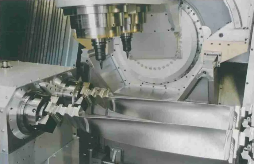
In the high-speed milling process, the smooth transition of the tool trajectory is the key technology to ensure the cutting quality. Insertion milling is one of the most effective methods to achieve efficient cutting, compared with other milling methods, it can significantly reduce the radial cutting force of the tool, effectively inhibit the cutting vibration, and in the cutting process of the blade, it has high processing efficiency for the parts of the tenon root, the edge plate, and the leaf body that need to remove a large margin.
CNC programming technology:
With the continuous development of CNC machining and automatic programming technology, intelligence, integration, and parallelization have become its development trend. CAPP / CAM can be used to integrate the automatic programming system for blade surface parts programming, and even some blade-efficient cutting machine tools will have process knowledge of the programming system integrated into the machine control system.
Chatter suppression technology:
Machining chatter suppression methods are mainly divided into online forecast control and offline predictive control.
The former is mainly through monitoring the actual machining system, vibration signal extraction, and vibration suppression under the pre-set control strategy. This approach puts high demands on the prediction system in many aspects, including fault tolerance, chattering control strategy, and sensitivity (speed of judgment).
The offline predictive control method is based on the stability limit diagram of the system cutting parameters, and the chatter suppression is realized by controlling the cutting process parameters and system structure.
Currently, the time domain simulation, semi-analytical, and analytical methods are the main methods to obtain the stability limit diagram of cutting parameters. In addition to the above two methods, some scholars have also proposed using the active vibration damping method to suppress chatter in the machining process.
2. Blade Precision forging technology
Blade precision forging technical adapts high-precision forging equipment, dependent on integrity inspection methods and auxiliary handle process to forge blank blades with high-quality and small machining allowance. The precision forging blade can more integrity keep the continuous metal streamlined sharp, ensure strength and load force of blades, and extremely raise feature and circle time of blades.
The precision forging blades have a small machining allowance, high strength, short time of machining, and high circle time, but a damping platform, front and rear edge parts of some blades still need to keep part machining allowance, all this is decided by the blade construct complex and precision forging feature at nowadays.
Precision forging blades is a comprehensive technology, so it needs high requirements for raw materials and the manufacturing process. Limited by process, part of precision forging blades still depends on machining to ensure surface quality and section size.
During the blade forming process, the previous and next processes must be strictly matched, and the deformation temperature, deformation speed, deformation degree, and metal flow direction of each process must be strictly controlled. At the same time, high requirements will be put on the table for the design of the precision blades, precision and strength of forging equipment, and precision of inspection and test of equipment.
3. Blade superplastic forming/diffusion bonding manufacturing technology
Superplastic forming is a forming process developed by utilizing the excellent plastic deformation capacity of certain materials under specific conditions.
Application of this progress can produce the blade of complex construct with high precision. At the same time, due to its excellent deformation ability, the manufactured parts have good processing repeatability and no rebound.
Diffusion bonding is a method of forming a connection by solid-state diffusion of atoms between the surfaces of the materials being connected under pressure that is not enough to cause plastic deformation and a temperature that is lower than the melting point of the workpieces being connected.
Superplastic forming/diffusion bonding technology gives full play to the advantages of the two processes. It has become more and more widely used in the application of forming hollow structures and is a good choice for forming hollow blades.
Taking advantage of the fact that the diffusion bonding temperature of titanium alloy is similar to its superplastic forming temperature, when processing blades, the two processes of forming and bonding can be completed in one process, saving heating and cooling time and improving the production efficiency of blades.
In addition, the blades manufactured using this technology do not require additional mechanical assembly and welding treatment, making the parts more integrated, which is of great significance for reducing the weight and increasing the thrust of aircraft engines (Figure 2). Rolls-Royce has continuously innovated on titanium alloy fan blades and has experienced the first generation of narrow-chord solid fan blades.
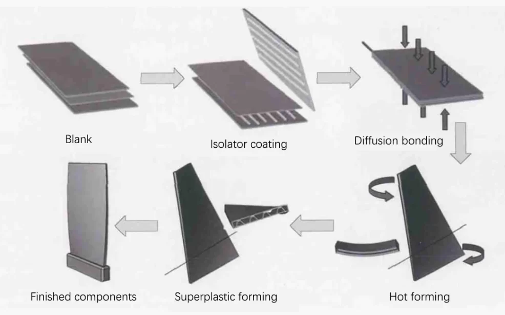
The second generation of honeycomb sandwich structure wide chord fan blades and TRENT 800, including the subsequent TRENT 1000 and TRENT XWB, all use the third generation of titanium alloy fan blades.
The blade adopts a new sandwich structure, that is, the honeycomb structure is replaced by the truss structure core, and is manufactured using superplastic forming/diffusion bonding technology, so that the blade increases in size while effectively controlling the structural weight.
Turbine blade manufacturing technology
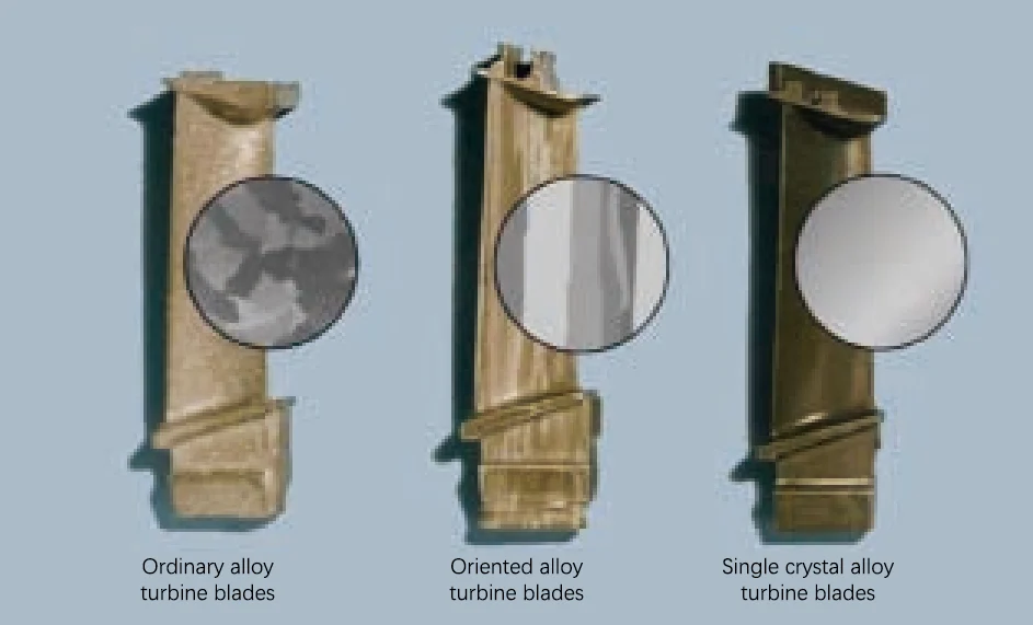
Due to the harsher environment in which turbine blades are located, more stringent requirements are placed on their materials and processing technology compared to fan/compressor blades. At present, the processing of turbine blades generally adopts precision casting (Figure 3), supplemented by other processing methods such as grinding.
1. Investment no-residue precision casting technology
Investment no-residue precision casting technology is a technology that can directly manufacture complex curved surfaces and eliminate the material removal process on the blade surface.
This technology can improve the working performance of the blade and increase its working life. It is often used to manufacture directional/single crystal hollow no-residue blades.
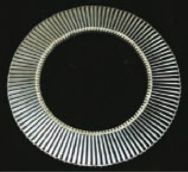
It has become an important development trend in the manufacturing technology of advanced aircraft engine turbine blades. For example, this technology is used to manufacture γ-TiAl alloy low-pressure turbine blades, as shown in Figure 4.
The key technology for investment in no-residue precision casting of hollow blades is to manufacture the ceramic core of the cooling structure.
The more efficient the cooling of the hollow turbine blade, the more complex its inner cavity structure, the more demanding the working conditions, and the more precise the corresponding ceramic core structure, so the control requirements for the dimensional accuracy of the ceramic core are also higher.
The most commonly used method for manufacturing ceramic cores is prefabrication of ceramic cores. This method can be used to cast cooling structures of various complex shapes. The main steps include pulping, pressing cores, core correction, furnace sintering, and strengthening treatment.
2. Directional solidification crystallization control technology
Directional solidification crystallization control technology refers to a casting process in which the molten alloy is crystallized and solidified in the direction opposite to the heat flow in the investment casting shell.
The turbine blades formed by this process have high resistance to thermal fatigue and thermal shock.
There are many early directional solidification technology methods, which can be roughly divided into the following categories: exothermic agent method, power reduction method, rapid solidification method, liquid metal cooling method, and fluid cooling method.
Nowadays, many new directional solidification technologies that combine the advantages of traditional technologies with the latest process methods are constantly emerging, including regional melting liquid metal cooling method, electromagnetic constraint forming directional solidification method, deep supercooling directional solidification method, laser ultra-high temperature gradient rapid solidification technology and continuous directional solidification technology.
3. Recrystallization suppression technology
The emergence of recrystallization will cause the high-temperature resistance of the original single-crystal alloy to decrease significantly.
During the blade manufacturing process, plastic deformation occurs due to mechanical treatment (such as sandblasting, mechanical polishing, etc.), followed by high-temperature treatment such as solid solution and annealing, or the effect of high-temperature and high-pressure gas during use, which may lead to the emergence of recrystallization.
Therefore, targeted research has been carried out at home and abroad, and methods such as pre-recovery heat treatment, carburizing, coating, and removal of surface deformation layer have been proposed to suppress recrystallization, and repair work has been carried out on recrystallized blades by adding boundary strengthening elements.
4. Other processing technologies
High-speed and powerful grinding technology.
World aviation powers have begun to study the application of high-speed and powerful grinding in blade manufacturing. For example, this technology can be used to process the tenon tooth shape of turbine blades at one time, which can greatly improve production efficiency.
The current development trend of grinding technology in various countries around the world is the research and development of CNC grinders with higher rigidity and precision, research and development of superhard abrasives and grinding tools, and further theoretical research and technical exploration of precision grinding and high-speed grinding.
As a new practical technology for advanced manufacturing, high-speed and ultra-high-speed grinding has attracted great attention from my country’s aviation engine industry and is an important development direction of domestic grinding technology in the future.
Adaptive processing technology is an important part of efficient and precise manufacturing technology for blades. This technology is mainly used for precision forging, precision machining of rolled blade edges, machining and repair of integral blade disks, CNC machining of complex hollow blades, and machining of complex curved surfaces with uneven allowances.
Manufacturing technology of composite blades for aircraft engines
Advanced composite materials are increasingly used in the fields of aviation and aerospace due to their lightweight, high strength, corrosion resistance, fatigue resistance, and many other characteristics.
Fan blades made of resin-based composite materials, fan/compressor blades made of metal-based composite materials, and turbine blades made of ceramic-based composite materials have become key technical means for reducing the weight and increasing the thrust of aircraft engines.
Manufacturing Technology of resin-based composite blades
Since GE began to develop and use resin-based composite fan blades in the 1970s, nearly 50 years of technical exploration and experience have developed a variety of commercial aircraft engine fan blades that integrate advanced materials and processes.
This involves the processing of composite materials, the preparation of preforms, and blade-forming-related technologies.
1. Composite cutting technology
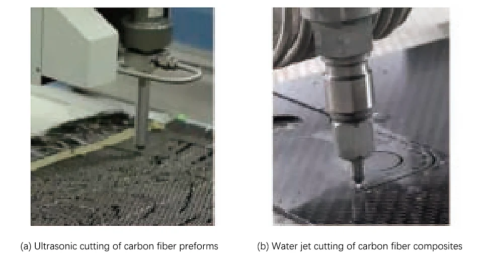
In the cutting of preforms and composite components, when using traditional drilling, milling, and other processes, due to the high hardness and brittleness of the fiber, changes in cutting force, tool wear, and other reasons, the surface of the workpiece may be incomplete, and even defects such as delamination, fiber pull-out, and detachment may occur.
In recent years, the application of non-traditional processing technologies in composite materials has become more mature. For example, ultrasonic cutting or laser processing can achieve high precision when processing carbon fiber preforms (Figure 5). Water jet processing has a lower cost for removing excess composite materials, and rotary ultrasonic processing has a greater advantage in making holes in the laminated structure of CFRP/Ti alloy.
2. Preform preparation technology
There are two main preparation processes for composite blade prefabrication, namely prepreg laying process and the 3D weaving process.
Prepreg laying process:
The use of the prepreg laying process to prepare preforms requires focusing on the plane-surface transformation cutting optimization of prepregs, the precise positioning of prepreg laying, and the puncture reinforcement between prepreg layers.
The layered slicing method is generally used in combination with an automatic cutting bed for transformation cutting optimization, the laser lofting method is used for precise positioning, and special equipment is used for interlayer puncture reinforcement.
In recent years, with the advancement of technology, the automatic fiber placement process (AFP) has also been successfully applied to the preparation of preforms. For example, Rolls-Royce has applied AFP technology to the composite fan blades of the TRENT series engines under development, realizing the automated production of its preforms.
3D weaving process:
The 3D weaving process is to interweave and cross the fibers in three-dimensional space in multiple directions in a regular manner to obtain a complete structure. This technology completely solves the problem of interlayer separation of the product and can greatly improve its structural performance.
At present, there are 4 commonly used 3D weaving methods, namely polar weaving, diagonal weaving, orthogonal weaving, and locking weaving. 3D weaving has many forms, such as two-step methods, four-step methods, multi-step methods, etc.
CFM’s LEAP-X engine fan blade is currently the only composite blade that uses 3D weaving technology to prepare preforms. The blade has unique advantages in impact resistance, fatigue resistance, and crack resistance due to its high specific strength and high specific modulus.
3. Blade forming technology
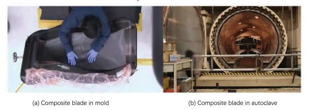
The fan blades of aircraft engines adopt the structure of the hyperbolic surface, large torsion, and variable cross-section. It is difficult to ensure the forming accuracy of parts by relying solely on the autoclave forming process. The closed mold forming process can well solve the problem of insufficient forming accuracy, so this technology has become the mainstream forming technology of composite fan blades (Figure 6).
In addition, with the continuous innovation of technology, the use of composite forming molds to replace metal molds and the use of mixed fibers to replace single-fiber fan blades have gradually become a development trend abroad.
Since the composite mold and the composite part itself have similar thermal expansion coefficients, the dimensional accuracy of the formed parts is guaranteed. In addition to the need to consider the mixing method and the optimal fiber ratio when laying the layers, the mixed fiber composite material is not much different from the single fiber blade in terms of the forming process.
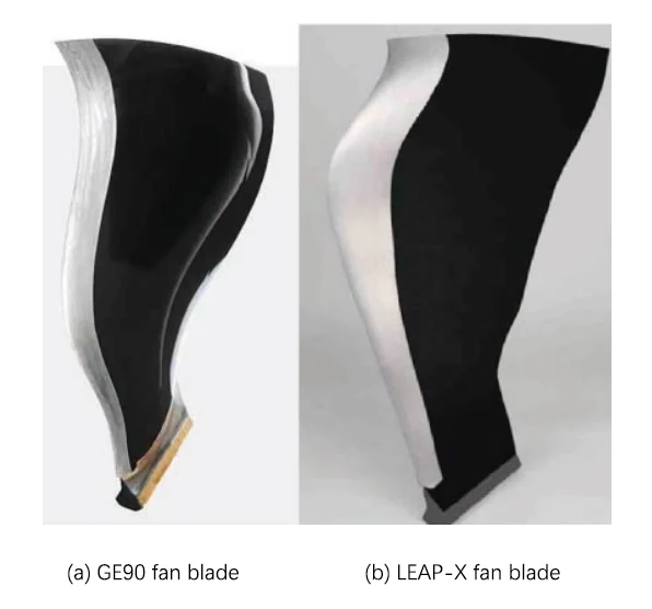
The two basic manufacturing processes of resin-based composite fan blades are prepreg placement/compression molding technology and 3D weaving/RTM molding technology.
The former refers to the technical means of manufacturing composite fan blades using prepreg as the molding raw material and the molding process as the molding method. It is mainly represented by the GE90 (see Figure 7 (a)) and GEnx engine fan blades produced by GE.
In addition, Rolls-Royce and GKN Group also jointly adopted this technology to develop fan blades for the TRENT series engines.
3D weaving/RTM molding technology refers to the technical means of using fiber tows to prepare preforms through 3D weaving, and then putting them into the molding mold to use the RTM process to manufacture composite fan blades. The main representative model is CFM’s LEAP-X engine fan blade (see Figure 7 (b)).
To improve the impact resistance of the blade, it is necessary to add metal reinforcement edges to the edge of the composite blade. The current methods for manufacturing metal reinforcement edges are mainly:
CNC machining method, superplastic forming/diffusion bonding process molding method, metal deposition molding method. GE uses CNC machining technology to process titanium alloy edging and the effect is good. Other related technologies have not been reported in the literature for application in active aircraft engines.
Metal-based composite blade manufacturing technology
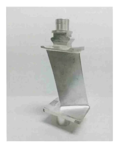
Metal-based composite materials have better specific strength, specific stiffness, and structural stability than traditional metal materials. Product performance can be designed on demand to achieve structural and functional integration (Figure 8).
P&W has successfully developed B/Al fan blades by combining plasma spraying with vacuum hot pressing. The blades have passed the test bench, corrosion resistance, and impact resistance tests, and are 40% lighter than the original titanium alloy blades. They have been successfully applied to the first-stage fan blades of JT8D and the third-stage fan blades of TF30;
Pratt & Whitney and TRM have successfully developed the first-stage fan blades and first-stage outlet guide blades of F100 by using B/Al prefabricated strips of plasma sprayed 6061Al, and have passed static load and thermal fatigue tests, with a weight reduction of 35%~40%;
Starting from the PW4084 engine, Pratt & Whitney has gradually used extruded silicon carbide particles reinforced by deformed aluminum alloy-based composites produced by DWA on fan outlet guide blades.
Its research and development work shows that the fan outlet guide vanes or compressor stator blades made of aluminum-based composite materials have better impact resistance than resin-based composite materials;
Pratt & Whitney has also successfully developed silicon carbide fiber reinforced titanium-based composite hollow fan blades with the help of the superplastic forming/diffusion bonding process, which can reduce the weight of the engine structure by 14%.
Ceramic-based composite blade manufacturing technology
Ceramic-based composite materials (CMC) not only retain the high-temperature resistance of ceramics but also have high mechanical strength and thermal cracking resistance.
At present, two main types of ceramic-based composite materials are most widely used, namely carbon fiber toughened silicon carbide (Cf/SiC) and silicon carbide fiber toughened silicon carbide (SiCf/SiC).
The former can be used at a temperature of up to 1650℃, and the latter can reach 1450℃. The manufacturing of ceramic-based composite turbine blades can be mainly divided into two stages: “blade prototype manufacturing” and “precision removal processing”.
1. Blade prototype manufacturing
Core stacking + outer layer weaving technology. When Western countries manufacture CMC blades with complex curved surfaces for the new generation of aircraft engines, the overall idea is to stack the core of the blade layer by layer and weave the outer layer for protection.
The manufacturing process is as follows:
(1) Make continuous reinforcing fibers into prepregs;
(2) Form the geometric body of complex components through precision prepreg slicing and assembly, and then add the outer cladding;
(3) Inject single crystal silicon into the graphite box at high temperature to achieve densification of the manufactured three-dimensional body;
(4) After applying surface protection, it becomes the prototype of the structural part, as shown in Figure 9.
3D printing technology. With the advancement of technology and the development of processes, 3D printing technology has gradually become one of the advanced means of manufacturing ceramic-based composite blades.
Some studies have successfully used gel injection molding technology to manufacture metal-toughened ceramic-based composite turbine blades.
The manufacturing process is as follows:
(1) Prepare the metal toughening skeleton of the turbine blade through the metal 3D printing process, and then form a ceramic interface layer on the surface of the metal toughening skeleton through vapor deposition;
(2) Combine the metal toughening skeleton with the ceramic interface layer with the light-cured resin mold of the turbine blade to obtain a resin mold with a metal toughening skeleton inside;
(3) Remove the resin mold through the chemical corrosion method, use vacuum freeze drying to remove moisture in the ceramic blank, and then sinter at 1200~1400℃ for 3~6h under a protective atmosphere to realize the prototype of porous composite turbine blade;
(4) Generate silicon carbide ceramics in the pores of the composite turbine blade through chemical vapor deposition for densification to realize the preparation of the ceramic-based composite turbine blade prototype.
2. Precision removal processing
The blade prototype formed by the above technology can only become a qualified product after further precision removal processing such as trimming and drilling.
Therefore, the processing technology that can meet the requirements of high-precision precision removal is one of the keys to manufacturing high-quality blades.
The CMC blade prototype not only requires precise trimming to achieve the required precision for matching but also requires cooling holes and mounting holes.
The main methods currently used in CMC cutting processing include water jet processing, electrospark processing, ultrasonic processing (including rotary ultrasonic processing), and laser processing.
Water jet processing is prone to tearing and surface collapse of materials, electro spark processing efficiency is low, ultrasonic processing requires precise compensation for tool wear and solves the problem of material collapse, and laser processing is difficult to avoid the impact of thermal effects.
In summary
In the use of removal processing technology to manufacture high-quality and efficient CMC engine blades, the key research directions are:
More precise CMC prepreg slicing and assembly; lower cost and less damage CMC compact part trimming and punching process; CMC mounting hole forming process and surface precision grinding, polishing, and other processing processes.